Single Turbo 1UZ MKII Supra Project

The 1UZFE EGR Delete Kit is available for sale here.
The engine was fitted today to check clearances for radiator, fans, manifolds, exhaust, hood clearance, and turbo placement. Using PeeWee's mounts (purchased pre-built from Nick), I mounted the engine with the mounts allowing for the most front clearance. (I.E., mounts farthest forward on engine block)


IMG_9259.jpg

I had to dig around for my old set of lower mounts, and found it easiest to mount the lowers to the uppers after seeing that one of the passenger manifold's (flipped driver's manifold) primaries was contacting the lower mount and preventing them from mating.

IMG_9271.jpg

I removed the passenger manifold, and set the engine on its perches.

IMG_9274.jpg

IMG_9285.jpg

IMG_9282.jpg

IMG_9289.jpg

Clearance from the back of the heads to the firewall is around 4-5 inches:

IMG_9292.jpg

IMG_9300.jpg

There was a surprising amount of room to work with around the manifolds and frame rails. The driver’s side cleared the steering shaft with the flipped manifolds easily, but is very close to the power steering lines to the steering gear. There was 3 inches of clearance from the lowest/widest valve cover mounting point to the brake proportioning valve on the driver's shock tower.

IMG_9304.jpg

IMG_9296.jpg

There was even enough room on the passenger side to install/remove the manifold without much fuss. There was 4 inches of clearance from the lowest/widest valve cover mounting point to the shock tower on the passenger side:

IMG_9302.jpg

The obstructing primary was trimmed to re-fit the manifold for clearance checking.

IMG_9316.jpg

IMG_9320.jpg

IMG_9321.jpg

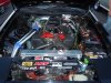
There was 6.5 inches of clearance from the radiator outlet to the radiator panel, and 7.5 inches from the alternator pulley to the radiator panel.

IMG_9306.jpg

The old radiator and fans were quickly installed to judge space availability:

IMG_9310.jpg

IMG_9308.jpg

The turbo was also judged for the best possible placement. The passenger side allows the downpipe to move between the shock tower and valve cover (above the manifold) and exit down and through the side. There should be enough room for a wastegate, and all the needed turbo manifold piping/braces.

IMG_9329.jpg

IMG_9331.jpg

IMG_9335.jpg

The hood closed with no issues with the manifold flipped around. I foresee no issues with clearance when the intercooler pipes are fabricated and mounted.
I am now thinking about what to do for a radiator. The driver's manifold needs a pipe to route to the passenger merge location, and I am worried about the lower rad hose outlet interfering with accessible routing. Also, I am worried about thicker aluminum radiators pushing the fans out even further and choking space up front.

I thought about mounting a radiator underneath the rad panel, but decided that was not the way to go since no viable options are there for inlets/outlets in an appropriate size. (Would need a 24”x14” radiator with suitable inlet/outlet) As of now, the Griffin 25241 looks like what I will go with. It is only 15.5 inches tall, which will allow it to sit a bit further in compared to the stock MKII radiator. Also, the cross flow inlet/outlets will better position the lower inlet to escape the driver's exhaust section.

http://www.summitracing.com/parts/GRI-1-25241-X/

I did alot of measuring and calculations, and I think I can actually fit the radiator (with a tiny bit of trimming on the rad panel) so that the fans will give a bit more clearance than what is currently available with the stock radiator.

More to come soon. Parts are coming in a steady flow, so lots of more projects should start springing up in the near future.

Thanks, -Mike
 
For the little power I am looking to make, I think these will work ok. People have made well over 450 WHP on stock flipped units, and I don't want to make near that power. Yes, they look quite ugly, but I will be radiusing a few of the bad primaries and most likely have them ceramic caoted when finished.

Also, I will be building a few very heavy duty braces to support a majority of the turbo's weight to the engine itself. I am not too worried about the flanges on the manifolds, as the manifolds themselves shouldn't be holding a majority of the turbo's weight.

I may change my mind. As you can tell, I tend to chase after perfection (or at least looks). If I find they don't suit my tastes, I may move to a log-style manifold setup or something else.

-Mike

intrigued to see the bracing you plan to make for the turbo. im watching this thread closely. lovin the build.
 
Flanges ???It is not weight..
It's heat and sealing qualities with boost
behind them..
Your aiming low boost [for the time being]
so heat may not be an issue..
 
For the radiator fans have you considered a dual pusher setup? I wanted the extra room for my supercharger so I mounted the fans on the front of the radiator. They are slightly less efficient in this configuration but a good high quality aluminum radiator more the makes up the difference. Even boosted my 1UZ only pushes the temp gauge up about 1/3 VS. 2/3 with the stock 7M-GE stock fans and radiator.
 

Attachments

  • DSCN0351  VER2   .jpg
    DSCN0351 VER2 .jpg
    200.1 KB · Views: 20
Thanks for all the replies gentlemen.


What year range Tundra manifolds should I look for? It seems the pre 2005 models are a log style, and so are the 05-06 models which also have an EGR tube that run across the length of the primaries. Either way, they both seem like they would work well and have beefy flanges.

These are listed on ebay as 05-06 Tundra manifolds for the 4.7L, but seem like 5.7L 3UR units?

$(KGrHqV,!jkE8FzF+ZRbBPD6SCdeQ!~~60_12.jpg


I could also just get a pair of the cheap chinese SS tundra "headers" that are all over ebay, but would rather not mess with SS as I have never welded it and all the other v-bands and pipe I have are mild steel.

$(KGrHqR,!n0E63WBWpP0BPFOOttg8g~~60_12.jpg


Also, is there any documentation for previous builds of how the dipstick will run with these manifolds? (is there any modification needed on to clear?)


I have thought about just using pusher fans with an aluminum radiator, but the $350 set of twin pullers I have are almost brand new and it would be a shame to have to retire them. I will have to gauge my options when I select a radiator and test fit it.


-Mike
 
Last edited:
I got my radiator from FF dynamics. It was the radiator, twin fans, and fan controller for about $400. I was very impressed with the quality and the fans they have move some serious air. How ever what really sold me was that there radiators have a lifetime warranty irregardless of what the car is built for. I had been planing on getting a Greddy radiator as they are very nice but there kinda pricey. FF dynamic is located in the USA and they offer free shipping to USA address's. I have been using mine for almost 2 years and all good so far. I have no affiliation with them, I just like there parts.

www.ffdynamics.com
 
I just used the stock flanges on my TT setup and 6 years of hard boosting later they are still fine with no sign of warp or leaks.

I also briefly used the cheapo Chinese (XS) stuff when the car was SC and they were surprising tough. WE had them glowing orange on the dyno, a coupla track days and 3 hillclimb rounds and they took all that abuse fine as well. They did need modding to get around the alternator when reversed though.
 
There's two std types of flanges..
I have used the thicker, I guess 10mm flange..
The bent plate I was sus on using them...
If they have been used with good results ???
Then very good...
I have my doubts on high power levels with unbalanced
exhaust flow on two of the primaries each side..??
 
Make new manifolds! :) This is going to look awesome. The IC piping hole in the side wall doesn't look to your standard?
 
Thanks for all the comments and suggestions folks. The traffic on this forum is alot slower than most I am use to, but all the feedback I am receiving is very helpful and smart!

I will have to debate the manifold situation. I think I might purchase the stock tundra manifolds, and try to make those work. As I can fabricate almost anything, my welding skills are marginal at best. Full manifold design (Times two) is a bit more than I want to take on, and the budget I have laid out doesn't really allow for me to have them fabricated by someone else.

The hole on the passenger inner fender is not of my usual standard. I did it when I was very young (and inexperienced) to make room for a CAI on my stock inline 6. The engine bay will be painted after all the fab work has been completed, to match the exterior of the car. I will be filling in all of the unused holes (bolts and openings), and repairing the little damage that leaky batteries have caused in that section of the car. The battery has long been relocated to the rear of the car, so the battery tray will be removed in its entirety.

Thanks everyone, hopefully more updates soon!

-Mike
 
Last edited:
yea not many people get on this forum as much as other, but i make a routine to at least check this thread every day. so much win goin on in here. haha
 
Not much happened this weekend. I had to babysit a pretty bad hangover for a majority of Saturday. :(

I took my time this weekend and fabricated a coil mount for both of the EDIS-4 coils. I wanted to secure them to the engine (not engine bay), so I decided a good place to mount them would be right behind the intake.

IMG_9360.jpg

The mount has spacers/washers that use upper intake bolts to hold it securely in place. These coils are surprisingly heavy, so I wanted to make sure I fabbed a beefy mount for them. Besides the washers and spacers, the unit is welded up using 3/16" x 1/2" flat stock.

IMG_9382.jpg

A bit of paint:

IMG_9394.jpg

Coils mounted:

IMG_9403.jpg

IMG_9405.jpg

IMG_9409.jpg

I am still waiting on the EDIS coil tower ends for my wires, then I will be building and routing the MSD wires. I will have to get "creative" for some of this, more on that later.
 
Time to take care of the ignition!

There is not a big aftermarket scene for performance 1UZ wires. Most that are available are way overpriced, and would not do me any good since I need custom length wires with Ford EDIS tower ends. I decided to make my own wires using one of the generic V8 MSD 8.5mm Super Conductor kits, and OEM/specialty pieces.

To keep a nice tight seal over the spark plug tubes, I needed to harvest the rubber seals from the tops of the old spark plug leads. I clipped the old leads off the wires, and investigated how to remove them:

IMG_9411.jpg

After some poking and prodding, it was evident that the hard plastic extenders were slipped into the rubber portion, and not glued. I trimmed the most I could of the old wire that was run through the top of the seal:

IMG_9426.jpg

The plastic extensions were as hard as a rock, and I couldn’t get the rubber seal to stretch past the holding rib on the plastic part. I decided instead to crush the brittle plastic end inside the seal by carefully squeezing the top assembly in a vice:

IMG_9429.jpg

Once the plastic started to crack and fragment into shards, I pulled the extension (with wire lead) out of the seal, and pulled any plastic bits out with a needle nose:

IMG_9430.jpg

The same process was followed for all the seals, until I had my set:

IMG_9433.jpg

The seals were a bit stiff and dried out, so I let them sit overnight in a bath of rubber protectant to help some oil seep back into the rubber. Soon I was ready with my supplies:

IMG_9483.jpg

I slipped the rejuvenated seals onto the wires close to the spark plug boots:

IMG_9487.jpg

The EDIS tower ends were supplies by Kingsborne.com, and came in a set of 10 boots and clips:

IMG_9489.jpg

A practice run to make sure the EDIS boots would fit over the beefy 8.5mm wires:

IMG_9491.jpg

The wires were inserted into the spark plug tubes, and the long boots were pressed gently with a flathead screwdriver on their top until I heard and felt the confident "click" of the wires securing onto the plugs.

IMG_9499.jpg

The seals were then easily slid down the wires and secured onto the spark plug tubes.

IMG_9509.jpg

The real challenge in running the wires was to make sure they all fit across the tightly packed coil towers, and looked good doing so. The Ford EDIS coils are closely packed, and the boots/clips are very bulky as well. The wires needed to be carefully routed to assure that nothing interfered with any of the wires making a good connection. Of course, I was also concerned with everything looking balanced and neatly routed.

It took me three different routing schemes before I found a route I liked. The challenge was to make sure that the paired waste-spark towers were routed to their respective cylinders that fire 360 degrees apart from each other. The routing I chose and the firing sequence are shown below:

FiringOrder.jpg

Using tape to hold wire to their towers, the lengths of the wires are marked with electrical tape. Wire separators keep the routing clean and balanced.

IMG_9514.jpg

After confirming the routing and lengths, I committed to building the EDIS tower ends on all the wires. The results are as follows:

IMG_9522.jpg

The plastic spark plug covers had halve-circles clearance cut with a Dremel to nicely separate and seal the wires coming out of the vale cover valley.

IMG_9530.jpg

The routing is very busy by the coils, but the symmetry between the sides is still to my liking.

IMG_9538.jpg

IMG_9549.jpg

With the wires Done, I think the next step is start building the AN lines. You can see some I have started in some of the pictures, but I haven’t made my mind entirely up with how I want to run my fuel lines.

I think I want to mount the Aeromotive regulator to the engine instead of the firewall. I am trying to keep the engine bay as clean as possible, with little to nothing actually on the firewall/inner fenders.

This is the proposed location, pending a swanky and sturdy bracket to hold it in place:

IMG_9551.jpg

Any ideas?

Thanks everyone,

-Mike


Top