Wiring my Stock 1UZ Again! Need Help Urgently!

The 1UZFE EGR Delete Kit is available for sale here.

Rawal4x4

New Member
Messages
38
Location
Rawalpindi, Pakistan
Hi everyone! I am in the process of rewiring my 1UZ after the initial job done on it turned out to be quite problematic. Using stock ECU and the original loom that came with the engine which was in pretty bad shape and cut up. The electrical shop who did the wiring did not have 1UZ experience and I ultimately had to take the wiring loom off and found things to be a bit of a mess.

I believe that the engine and ecu are from a JDM 1995ish Celsior UCF21 and I am using the Lextreme 4 page wiring diagram. There are some variations from the disgram as in I don't have a EGR and only about 35% of the color codes match up.

Would appreciate guidance as to whether I am heading in the correct direction! At this stage I have the following quick questions:

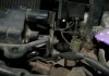
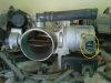
1. I cannot seem to find the knock sensors or their connectors on the loom and was wondering if this was it under the plenum/whatchamaycallit. If not what exactly is it?
file.jpg

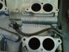
2. Just wanted to re-confirm that this is something to do with TRAC and I don't need it: file.jpg

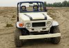
Got some more, will post later! Sorry for the fuzzy pics(which seem not to be coming through as embedded images so will try to attach) ! Many thanks in advance for your interest and comments. Here is a pic of my ride, was running quite well on good days but had issues with missing. I hope I can get it back on the road soon.
file.jpg
 

Attachments

  • 1UZ - Sensor Inside Plenum.jpg
    1UZ - Sensor Inside Plenum.jpg
    150 KB · Views: 31
  • 1UZ - Throttle Body Connector.jpg
    1UZ - Throttle Body Connector.jpg
    176.9 KB · Views: 27
  • 14DSC_3714.jpg
    14DSC_3714.jpg
    176.8 KB · Views: 34
1. Cold start injector. Not fitted to the two UCF21 engines that I have

2. Traction control

3. Nice shorty 40

I suspect a UZS151 Crown engine. Part no from ECU please, Will start with 89661-***** and I can tell you what it is out of. Those diagrams aint quite right but I have decoded the UCF21
 
Many thanks.

I believe the ECU is 89661 - 50241 or could be its 59241 (less likely) can't really tell from the pic, will reconfirm later. Its got 34P, 22P, 16P and 28P: file.jpg . Marking on the engine cover when I got it said UCF21: file.jpg

On 1, if thats the cold start injector, I wonder where I would connect it as I don't recall seeing it on the Lextreme diagram.

BTW where exactly do I find the knock sensor?
 

Attachments

  • file.jpg
    file.jpg
    270.6 KB · Views: 2
Last edited:
You're lucky that it's friday and I'm on the beers... Engine is ex UZS151 crown and the traction control is redundant. ECU is ex 9/91 UCF21 Celsior and I have just decoded the car side of it. Engine side of the diagrams on the site are correct car side is not. Give me a few days and I'll post up the list of what pin goes where as I need a few days for a bit of time out as I've reached a point where ones body say "No you need a rest"
 
Oh boy, that really makes my day! Always thought it was a Celsior engine given that the Lextreme engine variants write up says that "Crown - plenum has a “4 CAM 32” badge on the plenum and the plug covers say "Toyota"". Surprisingly we ever got it off the ground as supposedly difficult to run without trans and ECUs not interchangeable....

Will look forward to the UCF pinouts from your end which will probably be a big help for many others as well. Don't kill yourself over it though :) Have a great weekend and a bundle of thanks!


In the meantime I will try and see if I can find a 1995ish Crown UZS151 ECU around here and see if I can trade mine in.... Part number should be 89661 - 3A080 right?? Not holding my breathe though :)
 
Last edited:
The early UZS131 crowns had Toyota written on the LH cover with 4 cam 32 on the plenum. Later crowns have the same as the Celsior with toyota on the plenum and 4cam32 on the LH cover.
I would like to know why it looks like a UZS151 crown motor?

It has lower plastic covers even though it has the 20 series over cover. The throttle body has the larger breather to the tappet cover like the early motors and there is a cold start injector which the later motors dont have. Fuel pressure regulator is at the front where the later ones are at the back. The best way to tell is the early motors have 4 groups of 2 injectors while the later motors have the sequential injectors. Early ECu the header plug is in the centre of the ECU box and uses an alloy body karmin vortex air flow meter. Later motors have the header plug offset to one end of the ecu box and the plastic body air flow meter.

It looks like a early motor with a late model cover , ecu and air flow meter. The best way to tell is checking the original loom for the injector grouping. This loom may have been changed now to make it run and it looks like you have been driving it. I managed to receive two motors at the same time from different suppliers with incorrect ECUs so found out the differences between these two. I dont even care about the ECU numbers now. I simply apply early and late with correct airflows to there correct looms and it seems to work.

All the ECUs work fine without the trans although there are a few which have their own little issues.

The knock sensors are under the lower manifold each side of the valley just infront of the starter motor. You can usually see them down there.

Great truck. I have read your other forum posts a few times and it shows that boys are the same all over the world when it comes to their toys.
 
hehehe
I always say u get what u pay for
90% of shops think they know what they r doing
and only 5 or 10% do know what they are doing
and I always say. buy a complete engine set of someone
who knows their shit
and if they don't then find someone who does
a little extra cost at the start will save u three times as much in the end
 
Its easier for us in that respect Jim. In some parts of the world getting parts like this is extremely hard. The write up of this truck is one of the best I have seen and I think the builders did a fantastic job given the parts they had avaliable. I do completely agree when its easy (especially in NZ and Aus) that you should pay the few extra $$$$ in the beginning as it much cheaper in the end in most cases.
 
yes i know its easier but it shits me when 30 % of our phone calls are due to customer not doing their research
i guess the human brain/body is like that
instead of measure twice and cut once
we measure once and cut twice hahahhahahaah
and even then i always tell people the correct way to do things
but its usually to expensive so they do it another way and u know what the outcome is :)

if i got paid by how long i spent on the phone i could retire
 
these days the internet has a shitload of info
it helps alot of people but it also fks em up
i find alot of info which many cannot but i also loose business due to others finding the same info so i cant really complain
so you should have no explaination if u fk up because 80% of the info is out there
 
@Gloverman: Many thanks for your time, interest and appreciation here. Really appreciated.

Yes, we had been driving and blasting the truck around for a couple of months before I decided to open up the loom. The performance was not consistent, one day we would have engine missing / hesitation, backfiring and poor fuel efficiency and then on others we would be youtubing some madness eg. http://www.youtube.com/watch?v=d3EQrAaz2kE.

Its another story on the shop who wired the thing up in the first place, but we are planning to desert race this in a couple of months (guess poverty does make you do crazy things :)) and I wanted to make sure that we don't end up splitting wires in the sand....

Anyways, after having been living inside the wiring loom for past few days, (if I understand the difference correctly) I believe that the injection is actually sequential. There are individual wires with unique colours running to each injectors and the colour codes (at least for the injectors) pretty much match up to the 4 page Lextreme LS400 wiring diagrams. The injectors were wired up to the ECU where they should be according to the diagram and all seemed to be flowing well on the good days.....

@sideshow: Firstly, I've been following your posts on the forum for sometime and appreciate your post. Ours was one of the first and few V8 and 1UZ conversions down here in Rawalpindi Pakistan. While we have a vibrant second hand parts market out here, as yet we seem to only get the worst possible 1UZ pieces that probably no one else wants to touch. Parts availability is also a problem because there essentially are no 1UZ cars (noSCs, LSs, Celsiors, Soarers, maybe a handful of 1UZ Crowns) on\ the road out here. Secondly, while we can stand by the mechanical stuff, the auto electrical work down here is quite brass age and is done mostly by experience mainly by uneducated workmen who rarely go by the wiring diagrams. On engines which are more commonly used 2JZs and 3Ss they can do a half decent job but with the 1UZ they were in above their heads and as I said its surprising they got it off the ground. I guess you can do all the research you want but if you don't find the right parts or the right shop, you have to make do with what you have. Anyways as I said I really appreciate you posting up.

OK, I guess that takes care of the background :) I hope to bug you guys some more over the coming days with specific questions as I make slow progress through my loom. In light of all the above, I have decided to stick to what all I have and make do to the extent possible. Hopefully I can count on continuing support from the forum. Thanks Again!
 
Last edited:
Oh and I should add that the loom on the engine was cut I guess at somepoint where it would have gone into the the firwall. The electrical shop I worked with did not change anything inside the loom but had to extend the wires to hook it up to the ECU in the dash.... the ecu had different wiring colour codes but I figured from the net that it was off of a UCF21 and since the engine said UCF21, looked post 95 and said the right 4 cam stuff, we decided to give it a go given the take it or leave it attitude of the seller and lack of any alternates that would have been any better....
 
OK. Was away earlier and I finally got home and got a chance to check the loom. As it turns out the injector wires are doctored, it is an early engine with new gadgets and guess we have had it wired and running as sequential ignition... Haha!

@Gloverman: My apologies! Your analysis is spot on! I just hadn't really gotten thru to the injectors as I was having enough trouble figuring out why the LS400 diagram was not falling into place :)

@sideshow: Cut twice indeed... darn, that makes my weekend!


Anyways, I guess proceeding with things as is not an option any longer what do you guys suggest would be the best way forward:

1. Is it possible to use the current ECU at all or should I try and find an early UZS131 ecu? I can probably find it if its this one with three connectors: http://www.lextreme.com/forums/attachment.php?attachmentid=10268&d=1272323087

2. Is the correct wiring diagram for the engine the one on this thread : http://www.lextreme.com/forums/showthread.php?t=12635
Colour codes seem to be different again!

3. Will the current AFM work or do I have to look for the older alloy body one?


Once again thanks for all the help!
 
I beleive your ECU and airflow meter are a match. Your motor is not a UZS131 crown motor but could be a 141 crown or early Celsior. The second ecu that the celsior and ive seen on some 141 crown rans has the same pins 28/16/22/34 but with the ECU header in the centre. There are some other pins which change position too. Ill get some photos to explain and check out the diagrams.
 
The very best solution here would be an aftermarket ECU but I get the feeling that might not be an option. The main things you need to match are the ECU with the airflow meter along with the ignitors and injectors. Next getting the correct oxygen sensors , which is more important on the later motors as they throw codes and the oxygen sensors make a big difference to running. Injectors will make only a small difference and will still run. The correct wiring diagrams for your ECU are on here
http://www.lextreme.com/misc.html Use the 96 LS400 ones with the eight injector drives. Dont worry about colours. Just trust the pin diagrams. Seeing what you have managed to achieve so far im sure you can sort it. Otherwise you will need to try and find an early loom, ecu, air flow and ignitors. Mixing and matching is no fun. Good luck. Cheers
 
Thanks once again Gloverman! I got immersed in another set of projects and only have little time for the wiring while the truck and the engine gather dust :) I have a few very basic questions starting from:

What are the three sensors you see out here on the front right of the engine? Two facing up (green and dirty yellow) while one slightly below faces left (dirty orange)
file.jpg

Actually there is another one below the coil with red wire sticking out which I am not really sure about!
I know this info is probably out there but it sure isn't all that easy to come by!
Again, thanks for the help!
 

Attachments

  • IMG_3284.jpg
    IMG_3284.jpg
    75.3 KB · Views: 19
Last edited:
The green one is the EFI sensor which allows the ECU to know what the engine temp is. One side is earth and the other goes to THW on the ECU. Calibration is the same from early to late sensors so that will work fine with your ECU. The small single pin sensor is the one for the Temp gauge on the dash. It comes out of the loom in the dash plugs beside the ECU and is normally a yellow green wire. The Brown one is the cold start injector timer. As you have an early motor with a late loom you probiably wont use this one. The late ECU does not ran a cold start injector.
 
Thanks a million @Gloverman! But there is more :)

This one relates to the two connectors on the left (6 pin) and right (4 pin) of the injector (blue connector):
file.jpg

As I understand, the 6 pins connector has 2 each for 1x crank position and 2x cam position sensors, correct?

Understand that the 4 pin connector connects onto the left coil (2 pins) but not sure what the other two pins lead onto. Any clues?


Top