Wiring auto to wolf ECU

The 1UZFE EGR Delete Kit is available for sale here.
Hi Russ, Run a ground behind your button, set a pullup in the config and adjust the table to detect the gnd where want it to engage or disengage 4th. Understanding the wolf logic can be a challenge at times.
For the VSS (variable reluctor), one side goes to ground, the other to the wolf input pin.
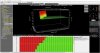
Here's some snips from a V550 for the VSS. Change the pin and set up the divider when your on the dyno.
 

Attachments

  • VSS_1.JPG
    VSS_1.JPG
    74.7 KB · Views: 4
  • VSS_2.JPG
    VSS_2.JPG
    44.4 KB · Views: 2
  • VSS_3.JPG
    VSS_3.JPG
    35.8 KB · Views: 2
Looks like fun! I am not a wolf expert, (more like a wolf in sheep's clothing...)
That "low side driver" I assume means it goes low when true. So 1Amp implies a relay is required?
Is that an output that would normally go TO a gearbox to say "Go into overdrive"? Or is it an output that goes to an indicator (OD on)?
Maybe call me sometime. Be great to catch up. (Yes, I have added your number..)


Jeff
 
This is what your config should look like (see attached), LS7 an input (renamed) with a pull-up resistor set.

Now setup your config table under it, then most likely will need to link it to a multicontroller.
 

Attachments

  • OD_setup.JPG
    OD_setup.JPG
    199.4 KB · Views: 5
This is what your config should look like (see attached), LS7 an input (renamed) with a pull-up resistor set.

Now setup your config table under it, then most likely will need to link it to a multicontroller.
Hi Ivan sorry not to get back to you sooner.

I went through all the configuration files I have and there is no micro controller for the AL7, This is the configuration used it basically looks like an on off switch.
My speed sensor config is the same as yours so not sure what to do with it configuration wise.
I did notice on your wolf wiring trans wiring diagram that the pins B5 Line control and B6 T/C lockup get power from the +12V line going to the ecu. I would have thought they would have power supplied from the transmission harness for these two solenoids, so dont understand why there is power added here as well.
al7.pngal7config.png

I am guessing the overdrive needs to be wired like the original as highlighted in the factory wiring diagram which gets power from the Ignition. Basically the wolf setup would connect to the factory wiring through an interface plug, so don't see it doing anything different.
overdrive wire.jpg
 
S1 & S2 are outputs that require +12V to switch the solenoids on. You should have assigned output pins for them. Both solenoids off is 4th gear (Overdrive) The outputs that drive these solenoids will be linked to a Multicontroller of which LS7 (if that's the input pin you're using for the OD switch) will be an input for. Depending on your logic, 4th gear (overdrive) will be enabled or disabled. That is if you are look for a gnd to allow the trans to shift to 4th gear or looking for a high to. You will need to create a 2D or 3D table for it depending on what parameters you want to use to engage or disable OD. Lets say you just use the switch then only a 2D table is required but if you also want to apply a speed parameter or a load parameter then you would need multiple tables, either 2D or 3D depending on the logic you use. Hope this helps.
 
Hi Jeff, yes the number called is mine. The wolf ecu controls the auto box as well as the engine which is part of the reason I used the wolf.
I understand the operation of the solenoids and how the box is set up, but I have one wire which has thrown me. It's B1 Aux LS7.
It's set up as O/D which I presume would be the button to turn overdrive off as everything else is connected. I guess what I am trying to figure out if it should have power on this line, in the Toyota diagram in a previous post above, it gets power through the line via the Ign1, gauge fuse,through the dash O/D light and then to O/D line between ECU and off Button, or whether it should run through a relay, or if it just needs to be grounded via a switch? this is the configuration page for the aux LS7.
View attachment 14041
pin out configuration

View attachment 14038

The speedo is going to be ECU configuration as the crown output is different to the soarer so not sure how it works out. I the wiring have it setup to get power from the main relay 12v and earthed and the VSS goes to the ECU. here is the speedo configuration page not sure what has to change here to get the right readings.
View attachment 14042
I've taken another look at the most recent screen shot you shared with me and it shows 1-2-3-4 (MCO2) that is it looks like you have set up MultiController 2 (MCO2) for all gears. I would then assume you have both solenoid (S1 & S2) linked under it. I'm not sure how that would work as my understanding is that an MCO can only control one output and can use multiple triggers. I would have expected to see as an example S1 (MCO1) & S2 (MCO2). Each controller drives an output and can use multiple triggers, can have 1 x 3D table and up to 4 x 2D tables. If I go back in time when I used the wolf to control the auto see picture.
 

Attachments

  • V550_Auto.JPG
    V550_Auto.JPG
    403 KB · Views: 1


Top