The Fish

The 1UZFE EGR Delete Kit is available for sale here.
I am glad at least 3 holes work and all you need is two additional holes. You should use round smooth spacers. They look better.

Yes, round, smooth spacers look better. But, these were cheap. Got them for like $10 for a bag of 30.:burnout:

I'm going to paint everything black, they won't be as ugly painted black.

KC
 
Got some bolts today that are long enough, some teaser pics. I can manage to get three holes to line up. Once I get the bracket on the engine, I will be able to determine where and how many holes will need to be drilled.
For mounting, it'll be stronger if you can get a 1 piece spacer tube rather than 2 pieces. A machinist can do that for you.
 
I'm still confused on how this works. Seems that some metered air doesn't make it to the engine, which is expecting the air. Also, if the air goes through the MAF again, it's metered again.

The air IS consumed by the engine. It is reirculated into the pipe between the MAF and the SC inlet so it passes through the SC again and then into the engine. During this time less air enters the inlet due to introduction of the recirculated pressurized air, so the fueling is momentarily reduced to compensate.

It works. Venting upstream of the MAF (venting not yet metered air) also works.

The bracket looks good - get some nice meaty single peice spacers.
 
For mounting, it'll be stronger if you can get a 1 piece spacer tube rather than 2 pieces. A machinist can do that for you.

Boosted2.0 said:
The bracket looks good - get some nice meaty single peice spacers.

I will at some point. Before I do, I need to get everything up and running. More importantly, I need to make sure belt alignment is correct before having spacers made.

The spacers in the pic look like they are pretty close to what I will need but I imagine I will need to add some washers, or possibly shave the spacers to adjust for belt alignment.

KC
 
Huge progress with some pics

Guys,

Couldn't do the intercooler mock up today, hasn't arrived yet. Couldn't do the fan conversion, still waiting on fan, fan clutch, and pulley.

But....I did put in an oil drain today. This is by no means the prettiest drain setup around. I do however feel it will function quite well.

Basic order of things.
1. I removed the steel oil pan.
2. Drilled a hole in the upper pan.
3. Threaded for a 1/4 NPT nipple.
4. Installed 1/4 nipple with sealer.
5. Used a 3/8 NPT to 1/4 NPT reducing coupler as a jam nut of sorts on the back side of the nipple.
6. Installed a 1/4 to 1/4 elbow.
7. Put in a plug for now.

First thing, I know some of you are already thinking a 1/4 inch isn't enough for a drain. Well, the inside diameter of the 1/4 nipple is the same size (very very slightly smaller) as a standard Vortech drain hose barb.

Vortech hose barb inside diatmeter.
1062842-1-8a733b758974063354c42015d59e07b888b0e5a7.jpg


1/4 NPT nipple inside diameter.
1062841-1-4555e6edd336414779810e7a22d735d698a2f874.jpg


If 3/8 i.d. hose is good enough for Vortech, it's good enough for me.

This is the 1/4 nipple used. Threaded into the upper pan from the outside.
1062847-1-e2211ad5cf800073b3c6349721f6025c99d8b41d.jpg


This is the 3/8 to 1/4 reducer used as a jam nut, threaded onto the nipple from the inside.
1062846-1-27e9a02a0b4af1956048d9cdf902d2f201e73d05.jpg


In this picture, the steel pan is removed along with the oil baffle. The hole is drilled into the driver's side, rearish of the upper pan. After drilling, I threaded using a 1/4 NPT tap.
1062840-1-f6459e3059e10cb66b08eab06a7a6c066f05252f.jpg


I installed the nipple from the outside of the pan with sealer. I've never been very good at making FIPG look good BTW.
1062844-1-da4995d07a8612cf7c06b8e11a51cb56efff9185.jpg


Installed the coupler on the inside of the pan, onto the nipple with more sealer. Again, never been good at making sealer look good.
1062839-1-afd70cba222d9202a78b37984f446b39e226744f.jpg


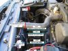
Installed a 1/4 NPT elbow and plug. For reference, this is the driver side of the engine. To the left of the elbow is the oil level sensor. The wire to the right is for the driver side O2 sensor (front sensor). It's a little hard to tell from the pic but the elbow is tilted slightly up. Also, the O2 sensor plug was put back into place and shouldn't interfere with the drain hose.
1062843-1-9f737dc541b3fd2130c502f7603f76db58fc2556.jpg


This took me about 3 hours to do and I spent about an hour and a half deciding where to drill. I was a bit nervous.

Again, I know it's a bit ugly, but I don't expect any problems from it. In fact, I think it will function quite well. I will run the drain hose in between the engine and the motor mount, straight to the supercharger.

One note on removing the steel pan. It's easy to remove but the motor needs to be jacked up a bit so that the pan can be tilted enough to clear the suspension crossmember.

This, to me, is a huge step in completing this project. With the drain out of the way, I may be boosted by Thanksgiving!

KC
 
Question on rods.

What's the best way to, without a doubt, determine which rods I have?

Should I call Lexus to compare part #'s?

What is the width of the skinny and beefy rods?

I was looking, but they are hard to see with only the steel pan off.

Thanks.

KC
 
If you have 1995 SC400, then u have stronger version of the rods. For the SC400 the change occur fron 1996 and on.

Sweet. I could see a couple of them with the pan off, but not enough access to measure anything. They seem pretty skinny, but I'm guessing that technically, even the stronger rods are still skinny compared to real high HP rods.

What do you think of my oil drain?

KC
 
BTW, it’s amazing that I have 132k on the car and can still see the cross hatch pattern on the cylinder walls.

KC
 

Attachments

  • TurboClearance.JPG
    TurboClearance.JPG
    79.8 KB · Views: 4
Here is a great example of Lexus and Toyota Rods
Lexus-Toyota-Rods.jpg

I really like your oil drainage. The oil return is above the oil level. I really dont like return the oil below the oil level. I think I see the oil level sensor. Did you return it on your left hand side? Clean it up it will look nice.
 
I really like your oil drainage. The oil return is above the oil level. I really dont like return the oil below the oil level. I think I see the oil level sensor. Did you return it on your left hand side? Clean it up it will look nice.

Yes, that is the oil level sensor, driver's side.

KC
 
Considering the SC motor ran at 10.1 compresison and 250hp/260tq from 92-95 before the OBD-II motors came in for 96+ with 10.4 compression and 260hp/270tq, I would be stunned if your motor is not identical to the ones coming off the lot in 92 with the beefier stock rods. I would bet the farm that the rod change occured during the OBD-I/II changeover.

David's previous statement definitely is affirmation of this.

The 1UZ in the LS400 got the OBD-II motor one year earlier, during the 95-00 model changeover, which is why 95 is labeled in the above photo.
 
Again, sweet!

I was already pretty sure I had the beefier rods, but I figure it doesn't hurt to double check.


Lex, have I ever mentioned how much I love this forum? :love:

KC


Top