Home made headers....

The 1UZFE EGR Delete Kit is available for sale here.

elliotaw

New Member
Messages
221
Location
Melbourne, Australia
I've been making up some stainless headers for the past few weeks. It's been a bit of a 'make it up as you go' kind of effort mainly due to my lack of experience, and the small amount of room left in my Ford Capri's engine bay. I've been closely watching the headers being built on here by cjsupra90 because it's pretty close to what I've been wanting to do. I've been hassling him for email help over the past weeks and he's really helped point my in the right direction with a few things. So thanks again for that mate.

Anyway, I too wanted to attempt to do a try Y design and make my own collectors. The head have been ported to 1.5" dia on my engine so my primaries are sized to match.

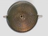
Heres my first attempt at a collector.
http://www.capripower.co.uk/board/index.php?act=attach&type=post&id=1648
http://www.capripower.co.uk/board/uploads/monthly_10_2008/post-44-1223541584_thumb.jpg
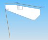
it was made up from a 180 degree bend which I marked out and cut with an angle grinder, then filed the mating faces as flat as I could (until I got bored).
http://www.capripower.co.uk/board/index.php?act=attach&type=post&id=1650
http://www.capripower.co.uk/board/uploads/monthly_10_2008/post-44-1223541598_thumb.jpg
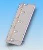
The outlet end has been made from a round transitional cone which I beat with a pair of hammers until the inlet end was oval to match the paired inlets.

This was my very first one. I made up 6 altogether and they got better and better each time, so appologies for the roughness.

Elliot
 
Here's my setup for purge welding the collectors.
I only have one gas bottle, so I have a T piece in the line and a hand valve so I can control the flow.

http://www.capripower.co.uk/board/index.php?act=attach&type=post&id=1699

http://www.capripower.co.uk/board/index.php?act=attach&type=post&id=1700

http://www.capripower.co.uk/board/index.php?act=attach&type=post&id=1701

This is not the first time I've done purge welding, but I dont have that much experience with it. So I am still on a steep learning curve with it.. so input and or critisism from anyone is more than welcome.

Heres the resulting purged weld

http://www.capripower.co.uk/board/index.php?act=attach&type=post&id=1702

Its not super pretty I know... but I'm happy. Its smooth which was my main goal.

Elliot
 
Started work on the header primaries. Here's progress after a few headaches trying to work out a route. I found that because of the size of the capri's engine bay, the location of the crossmember, power steering components and the engine mount it was physically impossible to run all 4 pipes down and out. I just couldnt figure out a way to get the front two pipes through the gap I have, so I came up with 2 or 3 different options and eventually decided to do this...

http://www.capripower.co.uk/board/index.php?act=attach&type=post&id=1715

http://www.capripower.co.uk/board/index.php?act=attach&type=post&id=1716

I'm sure there is a better solution that someone could come up with... but this is what I'm going with.

Elliot
 
Well im impressed so far,i know when i go and try to make mine it will look like ive stepped back a few metres and tried to weld.

Are you using stainless,is that why you are purge welding them??and why??
 
Nice work. What are your goals with this engine? You mentioned porting the ID of the exhaust ports to 1.5" What primary pipe size is that you are using? What about the secondary pipe size? Cam selection and RPM target?
 
Elliot, Glad you decided to throw a thread up about it on here.

No worries, You haven't been hassling me at all. Like I told ya, always here to help ;)

Keep the stuff coming.....

(side note:) Im finally working on the Left (passenger) side of mine as we speak.
 
Thanks for all your comments, I wasnt expecting that much of a response so soon, so thanks.

To answer the questions. Yes my heads have been ported to 1.5" diameter. I gave the guys that did the head work my flanges so they could port match them. My primaries are 1 5/8" O/D which gives a 1.5" bore so it all matches up nicely. I have used a local supplier for all the tube bends after the primaries. They stock a wide range of sizes (all metric) but had nothing close to 1 5/8 for the primaries so I had to source that from the states. My secondaries are 48mm I/D and then they will step upto 64mm I/D which is about 2.5". That size isnt final at this stage. I might still trim the transitions back to 2.25". Not 100% sure yet what to do, I need to check availablilty of the rest of the exhaust hardware for both sizes....and I dont know what size would be best for my application to be honest !!

The entire system will be stainless. Purge welding is done to achieve a smooth strong weld on the inside of the tubing as well as the outside. Anyone who has welded thin sheet metal from just one side will know what a mess it looks like on the other side. It gives a burnt appearance, isnt smooth, has rough sticking out bits and porosity. It goes like this because of the oxygen present, so when you make headers, you can fill the tube with the welding gas and it replaces the oxygen and so produces a welded appearance on both sides of the metal. Like I said already, I'm still learning this process, but I'm impressed by the results of what it does.

I dont have an ideal rpm range. The car will be used for weekend road use, track days and the odd strip day so its a bit of an all rounder I guess. I left cam choice to the guys at Kelford who selcted the same cams they usually sell for the street turbo engines. I guiess its reasnably high in lift/duration. I have the specs here somewhere if anyone wants to know.


Elliot
 
Hey Ill give you credit, unlike most people doing their own projects, you're getting some penitration!


Hey man just a tip. Don't make collectors like that. Not as effecient (shoot for 12* if possible), and curves are more expencive than straight pipe ;)
index.php

Love the purge caps, I use slices of bread. lol


More importantly, it can become impossible to actually weld the pipe in. You wind up having to weld it into the wall of the next pipe.

index.php
 
Slices of bread for purge caps.... thats an expensive way of making toast! I might try it myself!!

I dont mind the critisism on my collector design. This is my first ever header build. I check out the internet
looked at the different designs on their and thats kinda how I ended up doing them the way I am. Theres no real technical reason why, I just looked at the most expensive ones and figured you get what you pay for so lets copy they way they have done the expensive ones.

Heres where I'm upto

index.php


It would have been nice to be able to make equal length primaries, but I just dont have enough room. You can see the centre section of the longest primary has the middle part made up in quite a few parts.... it's just because thats where it runs real close to the steering CV.

Is there an ideal position to fit the O2 sensors? I am assuming right after the last merge collector ??

Elliot
 
Managed to squeeze in an hour a night so far this week to get this header into shape. Nearly into the single pipe stage now. Heres where I'm upto tonight. The apprentice wanted to be in the picture too seeing as he has been helping....

index.php


I also found some material at work to make the fittings for the O2 sensors. I'll turn them up on the lathe during lunch over the next couple of days so I can weld them in over the weekend (with any luck)
 
Been quite some time since I started making my headers for my 1UZ. Theyre finished now, there not perfect but for my first attempt I'm happy with how they have come out.

Heres some pictures :-

http://i1001.photobucket.com/albums/af134/elliotaw/header1.jpg?t=1261045827

http://i1001.photobucket.com/albums/af134/elliotaw/DSC03560.jpg

http://i1001.photobucket.com/albums/af134/elliotaw/02012010079.jpg

http://i1001.photobucket.com/albums/af134/elliotaw/03012010080.jpg

http://i1001.photobucket.com/albums/af134/elliotaw/10012010082.jpg

http://i1001.photobucket.com/albums/af134/elliotaw/purge.jpg

http://i1001.photobucket.com/albums/af134/elliotaw/DSC03569.jpg

http://www.youtube.com/watch?v=7lZRlB6s9K4

http://i1001.photobucket.com/albums/af134/elliotaw/cats1.jpg

http://i1001.photobucket.com/albums/af134/elliotaw/cats2.jpg

http://i1001.photobucket.com/albums/af134/elliotaw/cats3.jpg

http://i1001.photobucket.com/albums/af134/elliotaw/headerfinished.jpg

http://i1001.photobucket.com/albums/af134/elliotaw/catsfitted1.jpg

http://i1001.photobucket.com/albums/af134/elliotaw/catsfitted2.jpg

http://www.youtube.com/watch?v=IeeFCv_Ecw8

Thats about as far as I have got to date. My next problem is the car doesnt have much room underneath to fit any resonators off the shelf that I can find due to the chassis kit restricting the size. I am contemplating making my own from scratch and have been doing some research on the net on resonator design, but im just being overloaded with it all at the moment and dont know anyone in the know to ask so if anyone out there has any advice on how to deisign something that will work i'd be a happy listener....

Elliot
 
Last edited:
Been quite some time since I started making my headers for my 1UZ. Theyre finished now, there not perfect but for my first attempt I'm happy with how they have come out.

Heres some pictures :-

http://i1001.photobucket.com/albums/af134/elliotaw/header1.jpg?t=1261045827

http://i1001.photobucket.com/albums/af134/elliotaw/DSC03560.jpg

http://i1001.photobucket.com/albums/af134/elliotaw/02012010079.jpg

http://i1001.photobucket.com/albums/af134/elliotaw/03012010080.jpg

http://i1001.photobucket.com/albums/af134/elliotaw/10012010082.jpg

http://i1001.photobucket.com/albums/af134/elliotaw/purge.jpg

http://i1001.photobucket.com/albums/af134/elliotaw/DSC03569.jpg

http://www.youtube.com/watch?v=7lZRlB6s9K4

http://i1001.photobucket.com/albums/af134/elliotaw/cats1.jpg

http://i1001.photobucket.com/albums/af134/elliotaw/cats2.jpg

http://i1001.photobucket.com/albums/af134/elliotaw/cats3.jpg

http://i1001.photobucket.com/albums/af134/elliotaw/headerfinished.jpg

http://i1001.photobucket.com/albums/af134/elliotaw/catsfitted1.jpg

http://i1001.photobucket.com/albums/af134/elliotaw/catsfitted2.jpg

http://www.youtube.com/watch?v=IeeFCv_Ecw8

Thats about as far as I have got to date. My next problem is the car doesnt have much room underneath to fit any resonators off the shelf that I can find due to the chassis kit restricting the size. I am contemplating making my own from scratch and have been doing some research on the net on resonator design, but im just being overloaded with it all at the moment and dont know anyone in the know to ask so if anyone out there has any advice on how to deisign something that will work i'd be a happy listener....

Elliot

Man thats a double EE+ for effort on you project, I wouldnt even try to get close to doing something like that. Great job, sound good, thanks for the vid.
 
Very nice work. As suggested the collector design could be improved but at this point go with what you have.

I don't think your catalysts are metal core. Magnaflow appears to use carsound cats http://www.car-sound.com/04basics/04quality.asp
which use a ceramic core.

Metal substrate core catalysts that I have seen are round due to the way the core is wound. Looks kind of like corrugated cardboard on edge. Ceramic monolyth cores have have a "grid" look to them.

Below is a metal core
 

Attachments

  • catalyst.jpg
    catalyst.jpg
    92.6 KB · Views: 6
Last edited:
The cats have part #91006M stamped into them. I think the "M" designates them as metalic. I can take a close up shot for you if you like... I hope they are metallic...I will not be happy if i've been ripped off..haha..

Elliot
 
I have built some very nice exaust before... This is exceptional work... Looks very pro done. will like to see the dyno sheets on how they perform with the lenghs that you used. Please keep us posted


Top