Tools and Equipment Required
Brake clean (AT LEAST 2 cans)
17mm wrench or socket
14mm wrench or socket
11mm box wrench (in addition, an 11mm crescent wrench is also recommended)
10mm box wrench
10mm crescent wrench
1/2” Drive Ratchet (3/8” drive suggested)
Flat-blade screwdriver
Power cutoff wheel (or metal sheers)
Safety glasses and work gloves for the metal cutting process
Torque wrenches capable of 10-85 lb-ft settings
Small drip tray or several rags
Small funnel or suitable means of filling master cylinder reservoir
Anti-seize compound
Brake bleed bottle
1 pair of jack stands or other means of supporting vehicle
Plastic or non-marring mallet
|DOT 3 or 4 Brake Fluid. Check manufacturer’s recommendation for compatibility. (I recommend valvoline synthetic)
Jack
Jack stands
Step 1: Raise and support Vehicle
A level, stable and clean surface, suitable for supporting the vehicle on jack-stands, should be used for the installation.
Step 2: Remove wheels
Apply the parking brake, then break loose the lug nuts on both front wheels before jacking up the car. Warning: Never leave any vehicle supported with only a jack. Always use jack-stands.
Refer to the owner’s manual to identify the correct location of the jack for raising the vehicle. Jack up the vehicle, and secure it on a pair of jack stands, again referring to the owner’s manual for jack location joints.
To make it easier to access the brake line fittings, turn the steering either toward or away from the side that you’re working on, depending on the orientation of the caliper.
Step 3: Remove brake line
Warning: Spilled brake fluid will damage most painted surfaces, and should be cleaned off immediately. Take care to ensure that the cap is securely installed on the master cylinder. If it is loose or removed, it is likely that more fluid will drip during brake installation.
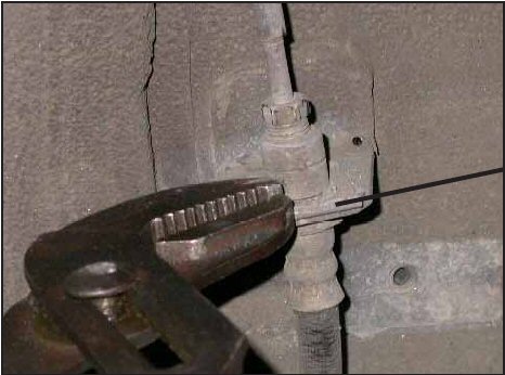
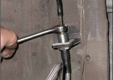
Loosen the hard line fitting, using a 10mm wrench (have a drip catching pan and rags to protect the control arms, and spray any left over off)
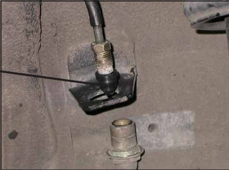
Remove the brake line retaining clip, using a pair of pliers or a flat-blade screwdriver.
Remove the hard line fitting, and place one of the rubber caps over the end of the hard line, to control fluid loss during the installation.
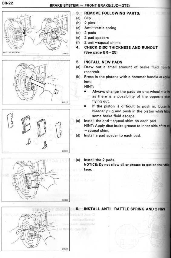
Step 4: Remove stock caliper and rotor
Remove the two stock caliper bolts, using a 17mm wrench or socket. (bolts may be VERY tight, so make sure you have a good grip on the bolt to prevent stripping)
Remove the caliper with the stock brake line attached. There may be some leakage from the open end of the brake line, especially if the pads/pistons on the caliper are retracted.
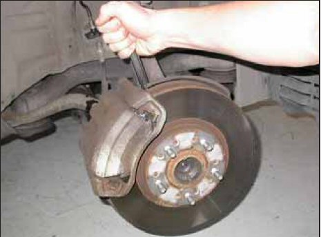
Remove the stock rotor, by pulling it off of the hub by hand. (Rotor may need to be banged off with mallet)
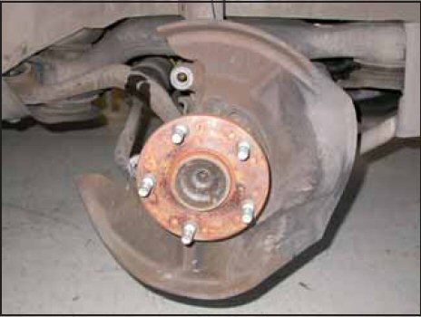
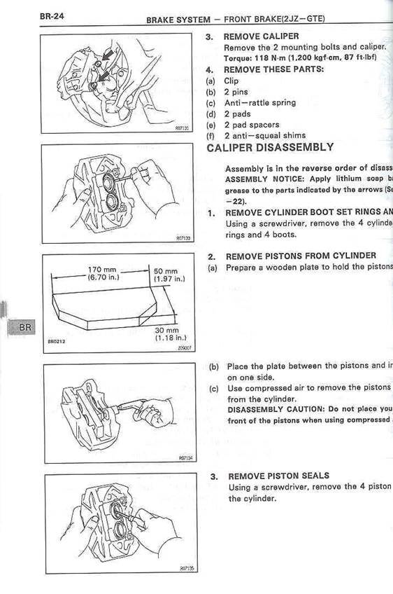
Step 5: Remove Dust shield
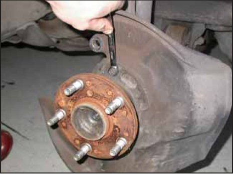
4 10mm bolts attach the dust cover to the hub assembly (2 on top and 2 on bottom)
Once the retaining screws have been removed, rotate the dust shield on the hub, so that the caliper clearance cutaway portion is accessible. Cut the mounting flange at either end of the cutaway portion of the dust shield, using a power cutoff wheel. Remove the cut portion of the mounting flange, and slide the dust shield off of the hub. The dust shield does not need to be retained.
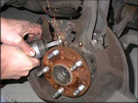
I used a pair of metal sheers. Get a good grip on the thinnest point (the spot where the cutter is) and twist hard, it should break and you can continue twisting until enough is out of the way to remove the dust cover.
Step 6: install supra rotors, calipers and pads
Place the rotors on the hub. Use the 2 17mm bolts to secure the supra TT caliper onto the mounting points and torque to 55 ft lbs Do not touch pad surface, clean rotors and pads with brake clean before installation (clean rotors after to remove oils from hands).
Make sure you install the pads so they are facing the rotor surface (yes people install them backwards)
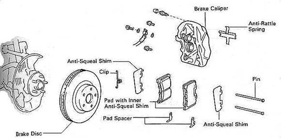
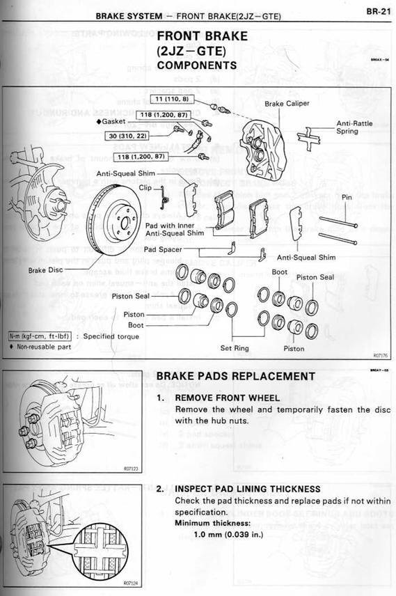
for more diagrams and tech infohttp://www.lexus.australia.as/technical_pages/soarer_high_performance_brake_upgrade.htm
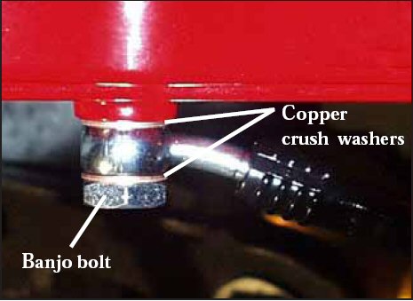
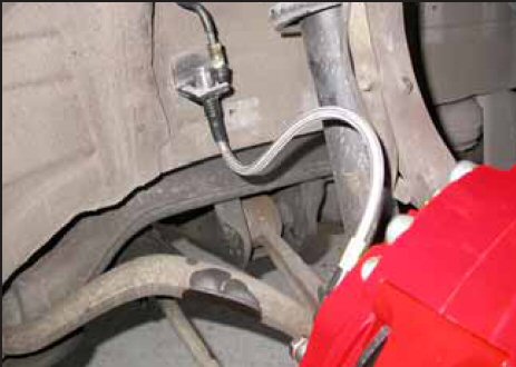
Step 7: SS Line Install
Install the caliper end of the stainless steel brake line by first placing a copper crush washer on either side of the banjo fitting, then inserting the banjo bolt into the caliper.
Insert the stainless steel brake line fitting through the chassis bracket, then reinstall the brake line retaining clip, ensuring that the prongs on the clip seat firmly into the grooves on the brake line fitting.
Use a mallet to gently tap the retaining clip into place.
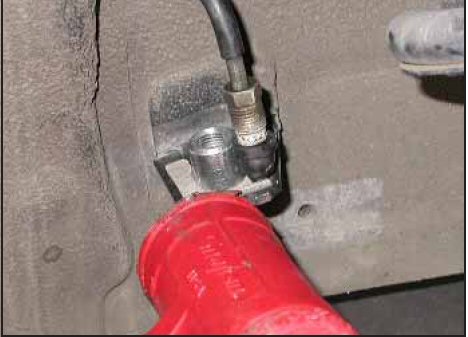
The brake line should form an S-curve as shown.
Remove the rubber cap from the chassis hard line, and screw the hard line fitting into the brake line fitting by hand for a few turns, to ensure that it is properly engaged.
Tighten the hard line fitting, using a 10mm wrench.
After securing the brake line, turn the wheels lock-to-lock, to ensure that the brake line is not binding in any way, nor interfering with any suspension component, including the CV boot and axle/drive shaft.
Step 8: Bleed brakes
Complete the installation on both sides of the vehicle before bleeding the system.
Warning: Double-check that the stainless steel brake lines you’ve just installed are not binding in any way, nor interfering with any suspension component, including the CV boot and the axle/drive shaft. Adjust each line, if necessary, by loosening the banjo bolt, and realigning the brake line, or by loosening the inboard end of the line, and slightly re-clocking the fitting.
Note: The calipers and lines will need to fill with fluid, quickly draining the master cylinder reservoir. Keep a close watch on the fluid level when initially bleeding the system. Do not allow the master cylinder reservoir to run dry, and to draw in air. Doing so may result in the brake system needing to be serviced by a certified brake technician.
Bleed the brake system, using an 11mm box wrench, to loosen the bleed screws. The sequence for bleeding the brakes should be: (easier done with 2nd person to loosen and tighten bolt)
1. Loosen right caliper bleed screw, press pedal all the way down, while pedal is down retighten, repeat until you do not see bubbles in the bleed line
2. Loosen left caliper bleed screw, press pedal all the way down, while pedal is down retighten, repeat until you do not see bubbles in the bleed line
After initially bleeding the system, gently tap the caliper body with a mallet to dislodge any small air bubbles, then re-bleed the brakes.
After bleeding, apply constant pressure to the brake pedal, and check all connections – including bleed screws, and both ends of the brake line – for leaks. Make sure the pedal feel is good and consistent.
Warning: Brake fluid will damage most painted surfaces. Immediately clean spilled brake fluid from any painted surface, including the caliper. Though caliper paint is designed to resist harsh chemicals, prolonged exposure will damage the finish (just try not to get any on the calipers)
Step 9: Reinstall Wheels
It is very important to check the wheel-to-caliper clearance before installing wheels!
Reinstall the wheels, and torque the lug nuts to 80 ft. lbs. It may be necessary to snug the bolts before lowering the vehicle, and to then torque the wheels when the car is on the ground.
Carefully test-drive the vehicle in a safe area, at low speed, to ensure that all components are working correctly.
Rotor and Pad Bed-in
Note: Bedding-in of pads should not be done in poor weather conditions, nor on wet roads.
After completing the installation, make a series of 10 stops from 60 to 5-10 MPH. At the end of each stop, immediately accelerate to 60 again for the next stop. Run all stops in one cycle. During the 60 to 5-10 MPH cycle of stops, the exact speed is not critical. Accelerate to approximately 60, then begin braking. As you approach 5-10 MPH, it is not necessary to watch the speedometer.
Keep your eyes on the road, and approximate your speed at the end of each stop.
DO NOT COME TO A COMPLETE STOP, WHILE LEAVING YOUR FOOT ON THE BRAKE PEDAL, AS YOU MAY IMPRINT PAD MATERIAL ONTO THE ROTOR, CAUSING A VIBRATION.
After the final stop of each cycle, drive as much as possible without using the brakes, to cool off the system. Ideally, the brakes should be allowed to cool to ambient temperature before using them again.
PLEASE BE SAFE AND DO THIS ON A HIGHWAY LATE AT NIGHT OR IN A LOW TRAFFIC AREA WITH FEW STOP LIGHTS, DON’T BE STUPID.
Thanks
ALSC and special thanks to Stop Tech for their write up (I used their tools check list and many images)
Complete Conversion Package includes:
* Brand new Supra TT front calipers
* Brand new Supra TT front calipers shim kit
* Brand new Supra TT Brake pads
* Brand new drilled and slotted rotors
* Stainless Steel Braided Brake Lines are not included in the above kit and its $120 upgrade. Once again, this is for the first generation GS300, SC300 and IS300