85 pickup - 1UZ swap with R150 transmision, MS3X stand alone ECU and 112 supercharger.

The 1UZFE EGR Delete Kit is available for sale here.

84pickup1uz

Fun Factor Garage - Canada Eh!
Messages
41
Location
Canada
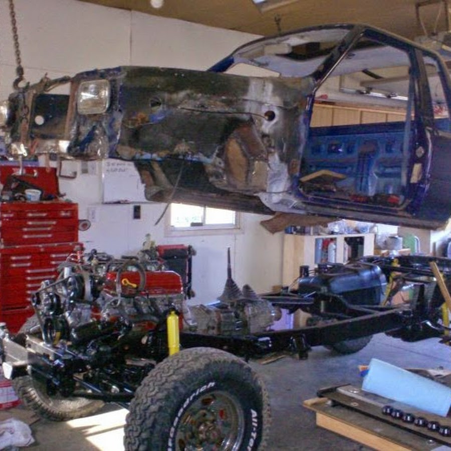
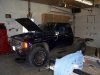
Just getting started on the physical work on this project. I've been doing research for several months and have acumulated a small mountain of cardboard boxes (parts) in the corner of my shop.

This truck project itself was started 10 years ago and at the time I had only access to a domestic engine (ford mustang 5.0). I will do a video on some of the 10-year-old work at some point later. I've recently sold off the highly tuned ford motor and purchased a 1UZ V8 from a 94 SC400.

The project was abruptly interrupted due to health complications with my firstborn son (who is fine now by the way). It was further delayed by several years while I helped build another vehicle for a younger family member. He has since passed away. Family always comes first in my life so this project has sat until recently.

When I retrieved the truck from storage I found a raccoon's nest in the cab complete with a large pile of dung! That was nasty! I could have filmed my own version of "ROADKILL" !! I ended up gutting most of the interior and the entire wiring harness. I've since bought a second 86 pickup for the parts I need to finish this one.

I am not a big fan of typing so I will be posting videos here fairly regularly. Here is my first video


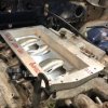
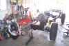
The engine - first gen non vvt out of a 94 SC400

engine.jpg

The Transmission is an R150F with down under bell housing and gear-driven transfer with 4.8:1 gears, dual shifter and upgraded from the output shaft. This came out of a serious rock crawler! I have a second transmission with fewer hard miles on it. Using this one for mock-up and to acquire all the adapter parts needed in one purchase.

trans.jpg

This is the ECU I just finished building Megasquirt version 3X
ecu.jpg

And this is an option! Note the spare intake manifold in the background. Planning to fab my own manifold. That should make for some entertainment.

supercharger.jpg

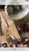
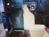
The mess from the Racoon! They made the front footwell into the latrine. I had already removed the large pile of dung at this point. The nest was behind the seats. It was nasty! the truck was stored inside but had no windows and the interior was mostly removed and in the box. They chewed on everything and crapped everywhere!
racoon.jpg


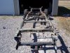
Here is a few pictures from 10 years ago just to set the stage.
 

Attachments

  • Picture 019.jpg
    Picture 019.jpg
    413.4 KB · Views: 10
  • Kelowna Walkerton 002.jpg
    Kelowna Walkerton 002.jpg
    919.9 KB · Views: 11
  • Picture 194.jpg
    Picture 194.jpg
    885.1 KB · Views: 10
  • Picture 341.jpg
    Picture 341.jpg
    423.1 KB · Views: 8
Last edited:
Thanks Kelvin! Watched just about every video you've made. Might need to source some stuff from you at some point although I actaully work for the local Toyota distributor so anything still in stock is not normally a problem.
 
Made some progress in the last couple of days. Got the R150 Transmission mocked up under the truck and sitting on the cross member. Going to make a new cross member/skid plate but need to get the motor mounts built and the drive shafts set up.

Lots more room than with the Ford motor. Should have enough room for a full puller rad fan even with my huge sprint car 3 core aluminum rad! That sucker is beefy!

1577209160056.png


Reusing the ford motor mounts but will need to modify to suit the 1UZ. Mostly just the mounting plates I think and I like the fact that they are adjustable back and forth and are rebuildable with just a set of Polly spring bushings.

1577209327077.png

Also stripped the motor a bit to make it easier to work on when I stick it in the truck. Took off the manifolds and old motor mounts. Removed wiring harness (loom!) and the intake manifold. Broke the typical plugs. found some critter nests under the intake.

Fooling around with the supercharger location. It will sit pretty high to accommodate the cobra intercooler which is 3.5 inches deep.. It's just sitting on the stock lower manifold at the moment but seems to be in about the right place. Time will tell. Will be interesting to see how much space we have on the hood. Might opt for a lower profile intercooler option but that will be completely custom not that the manifold it not custom to start with. Lots of fabrication and tig welding ahead


1577208873483.png

For more see my Youtube Channel


Attachments

  • 1577209199360.png
    1577209199360.png
    392.8 KB · Views: 4
Last edited:
1577674828801.png

The motor is installed in the truck and I am working on motor mounts and positioning.

Supercharger and Intercooler:
The supercharger will need to go lower to clear the hood. I had planned to use the stock cobra style intercooler but its simply too tall and also very pricey to purchase.

The plan is to now use a heater core designed for ford F150 as an intercooler core. In doing so I can lower the manifold flange by close to 2 inches and it will make it reasonably easy to fabricate the manifold around it and still clear the hood. As far as efficiency well I will simply have to speculate. The surface area of the core element is basically the same it's just shorter and wider. The inlet and outlet tubes are both on the same end and have provisions for O rings. Overall dimensions are similar to the supercharger flange. More on how I plan to do this later. For now, we will invest $50 in the purchase of the core for fitment and mock-up. The core is 5.25" x 7.75" x 1.2"

1577677430762.png


Steering Shaft:

The clamp bolt on the steering shaft does hit on the corner of the rocker cover. No issues as this is not part of the telescopic part of the shaft and I could just remove the pinch bolt and weld it solid to the shaft. I could probably just use a smaller-headed bolt too. I am not sure the one in there is a factory. It looks too big. I Will wait on this one as I do plan to install a different steering shaft anyway (the one from the parts truck outside) as I will at some point to convert to "High Steering" and will need the newer steering gear which will mount farther forward and have a longer shaft. Took all the required measurements today off the other truck. The newer shaft is a smaller diameter and will have much more clearance when installed.

Oil Pan:

The oil pan is another issue. SC400 mid oil pan is directly above the front axle housing. I will have more on that later as I ordered a kit to build a new rear sump pan to clear everything. An LS stock front sump pan would work but not with the high steering I plan to install at some point and would also mean ditching the front stabilizer bar. The new custom oil pan was the best and cheapest option. Still cost me a small bundle of cash and some time to weld it up but I will get a perfect fit that way and no worries later about clearance. There is the option of just buying the flange but it was still $160 and would mean spending a lot more time-bending sheet metal.

1577676969321.png

Motor Mounts:

Using the old mounts I had from the ford motor and they work well with only modifications to the mounting plates on the engine side.
I just trimmed them down and drilled holes in them to line up with the mounting holes on the block.

The picture shows the casting of the head in the way of the engine side. I will get some better angles later.

1577672124382.png

Exhaust manifolds and Headers:

Also messing around with exhaust manifolds. Started off with SC400 manifolds which I am told would fit with the flanges removed. They do but very close to the frame on the passenger side with the engine centred between the frame rails. They actually touched on my old fuel lines which were mounted on the inside of the frame.

I had also purchased some Tundra 2uz headers off of eBay which I had planned to modify as an option. For the price, they were worth buying just to try them.

1577675331510.png

Another fellow posted his installation of these same headers and had taken pictures of his modified driver's side. I had planned to do the same once I got the truck running. It looked like a lot of work to modify the driver's side. He had to cut off the front tube and relocated it lower to clear the steering.

Decided to bolt them up and see how they fit and they fit surprisingly well! I had to remove the flanges like the SC400 units but they actually fit better than the SC400 manifolds!

The driver's side needed both the flange and the O2 sensor bung removed and is currently a little close to the top of the frame rail but in my case, i had to do nothing else. I guess that's because my truck is a straight axle truck which allows me to install the engine at close to factory height. and therefore no issues with the steering.

I plan to lift the motor up on the mounts about a 1/4 inch (5mm) using some more substantial mounting plates on the block just to be sure. I need to do that anyway as my driveline angle is off my 2 degrees according to the pinion angle of the rear differential.

Here is the passenger side from the front and from the side through the fender well.

headers passenger.jpg

headers passenger 2.jpg

The driver's side is a little tighter but clears everything. Currently only a finger's width between the frame and the collector. Will raise the motor just to be sure.

headers.jpg

Currently only a finger's width between the frame and the collector. Will raise the motor just to be sure.


headers drivers fender.jpg
As a result, I am just going to use the headers. They are polished stainless!!. It kinda makes the rest of the truck look rough but that will soon change. For the money, I can't go wrong. Ordered some 409 stainless 2.25" J bends to make the cross-over pipe along with some really nice V-band clamps and a stainless 2 into 1 collector. The entire exhaust is now going to be mandrel-bent stainless as the back half is made with a modified TRD tundra kit.
 

Attachments

  • motor mount.jpg
    motor mount.jpg
    121.4 KB · Views: 3
Last edited:
Ordered a bunch of stuff to build the exhaust system and related it to the fabrication of the intake manifold. Also started working on the front of the motor and reworking the required plumbing for the power steering and oil filter.

used the banjo bolt style fitting from the SC line and the steering box end fitting from the 22R line. I ground off the crimps and had the local hydraulic shop crimp on a new section of high-pressure hose. Unfortunately, my original 22R line end was badly mangled so I ended up having to add a 3/8 joint into the line. Actually, this provided an added benefit of permitting the indexing of the line to be adjusted as needed.

this is the remaining part of the crimp on the power steering pump side. The local hydraulic shop was able to crimp a new hose onto this.

1578342663799.png

Had planned to do the same on the other end but the line fitting at the crimp did not survive the grinding off of the crimp like the other end. Just made sense to crimp a new steel line fitting on the hose and then join with a female flare fitting.

1578342942264.png

Runs across the front adjacent to the custom frame cross member where it clears all the belts and such. You can see my oil filter will not work with the stock adaptor either. The strut rod is needed for my stock drag link steering. Some of the other parts are just sitting on the motor in this picture.

1578343478387.png
 
Last edited:
My Intake is back from the machine shop. Basically, I hacked the top half off the lower manifold with my angle grinder and had my local machine shop deck the manifold level with the bosses for the injectors. I was planning to weld a plate on top of this and then build a box on top of that for the intercooler and supercharger to sit on.

The machinist suggested I simply bolt the plate on and pointed out that there is lots of material in 8 places to drill and tap the flat surface created. He then suggested brazing the two bolted surfaces or using high-quality aluminum epoxy to bond the two surfaces. I highly respect this machinist. He builts some pretty high-end drag and tractor puller motors so it's worth investigating.

Did my homework tonight. His ideas have merit and I can always tig weld the plate on if the first or second method does not work out. I like the idea of not having to deal with warpage in the manifold and plate. I will buy some super 6 brazing rods and experiment with some scrap manifold and aluminum. I think it will work really well here from what I can see online.

The epoxy I found is rated at 6000 lbs sheer force and up to 600 lbs line pressure when used on aluminum. Plenty of strength considering there will also be 8 bolts clamping the surfaces together. Its also rated for heat up to 400 degrees. If my motor ever gets that hot I have many other issues.

Here is the machined manifold (still needs cleaning) with tentative locations for the bolts marked out. Lots of exposer on the two ends but if the epoxy or brazing does its job there will be no issues. The bolts will take the load and also clamp the plate down. The epoxy will bond the two flat surfaces and act as a gasket.

1578408021666.png

Will experiment with the brazing rod and with the epoxy on some scrap and see how it works.
 
Last edited:
Lots of planning is being done but not a lot of hands-on work. I've started working on the intercooler box and manifold for the supercharger. I have enough hood clearance on the truck by the looks of things to allow a 2" thick intercooler. I had bought the heater core unit as an experiment but after running the numbers I need something with more surface area. Cannot find a suitable "heater core" which will fit nicely in the space I have. I just pulled the trigger on buying a complete Rad for a Honda. The entire radiator with shipping was $72.00 CAD.

The plan is to slice off one side of the rad to harvest the appropriate size chunk of aluminum core. Based on the picture I should be able to maintain the tank on the one end and just weld up the end that's open from the cut. The other end will need to be custom as I plan to have a two-pass setup with the in the waterline and the out-water line on the same end. The intercooler core will be 13.75" x 6" x 2" which has slightly more surface area as the cobra intercooler. 162 Square inches vs the cobra with 147.

The good news is the remaining part of the rad is actually the right size for mounting in the grill of the truck. If my tig welding turns out good on the manifold parts I will just modify the remaining rad chunk it to make the heat exchanger. It might or might not be worth the effort. There is lots of import air to water intercoolers available for less than $100. Time will tell.


1579111971713.png

I've also finished the work needed to design the mounting plates for the manifold and supercharger. I used some dye on the parts and some cardboard to produce some really accurate templates. The material used is gasket material as these could also be used as gaskets in the long run. I find it much easier to take these into the house for measurements when working on the computer cad program than the actual parts and everything is on the same plane. I was also able to scan them and make jpeg images which I loaded to the cam program to allow a trace over the process to get the port shape exact as well as ensure the plate for the supercharger has the exact same angles on the tabs (the edges line up all the way around)! I might share the resulting files if there is interest.

Once the rad shows up and I am able to finalize the dimensions its off the "Water Jet Place" to have it all cut out!!

Here is the templates. The numbers are my rough coordinates for the ports. Did one the long way and then the rest by trace once the picture was properly scaled on the CAD program. Both are upside down in the images. The notched corner is to clear the water bridge.

1579112441717.png 1579112566778.png

I will share the 3d Model once I have the intercooler specs finalized (the parts in between)

I also found a chunk of insulator material so I will incorporate a 1/2" layer in the manifold stack at the very bottom to reduce the heat soak into the intercooler and charger above. It will sit directly on the plate shown on the right above.
 
Last edited:
Finished my cad drawings of the manifold today. May add a few rounded edges and clean up the port opening a little but the majority is done. The yellow layer is a composite spacer. I might make it thicker and replace the alumium second layer. I designed the manifold to work with or without the intercooler spacer which is the second layer from the top.

Any advice anyone has please share!

1579322273879.png
 
Last edited:
Started on the engine wiring today. Thanks to Kelvin's videos's I have the wiring well in hand!!

I basically got all the extra wires identified and pulled from the factory harness (loom!) I left the extra wires in the main bundle so I can re-purpose them for new items or things I need to rework. It's a good wire and it saves having the thread the rubber boot at the engine with new wires as I add them. That rubber boot will be maintained to protect the wiring where it transitions to the firewall from the motor (Engine!)

Priority other than stripping out the traction control and transmission wiring looms is to modify the injector wiring to make it sequential. It's currently banked with only two trigger wires and a 12v power feed. I will need to split the trigger wires into eight separate wires and will re-purpose many of the transmission wires as well as the original ignitor wires for this new function.

I also need to add wiring and plugs for the "coil on plug" ignition. For this, I salvaged the wiring and plugs complete from two Celica wiring harnesses I had in my pile of leftover wiring here in my shop. I just cut the entire wiring out of the Celica harnesses and will add it to the 1UZ harness when I get a chance to lay it on the motor. No splices are needed!

Since my new intake manifold will hang over the top of the rear water bridge I will also lose most of the plastic wire loom pieces on the rear of the engine. With some luck, I can replace most of this with braid before I put all the new terminals and plugs on.

Also removed the wiring for the hydraulic fan and igniters and will relocate the stepper motor/idle air control and the TPS wires to the new location of the Ford throttle body/plenum on the passenger side above the rocker cover. I will change the MAF wiring to suit the bigger ford sensor. I plan to leave the canister purge on the motor at this point so I am leaving it basically in the stock location but on the opposite side from the Lexus as my canister is on the passenger side.

EGR electrical wiring will mostly be removed from other than two wires to run the switching valve for the liquid-cooled Ford EGR in the back of the supercharger. It's operated by ported vacuum with an interrupting valve that runs on a duty cycle. Where I live here in Canada the "MOE" or "Ministry of Environment" does not require a formal inspection for vehicles this old but does perform roadside spot checks. The EGR needs to be present and reasonably operational if I get stopped which is likely to happen. I plan to hijack the water injection table in the MS3 to provide a duty cycle map for the EGR. This is optional but making it work properly might aid with engine combustion temps and minor improvement in cruise fuel mileage. The table is controlled by MAP and TPS sensors and allows a specific duty cycle in each cell so it should allow for some tuning once the truck is operational.

I will leave the stock O2 sensor wires and will add a separate set for the wideband sensors. Once its tuned I would like to recover my wideband controller as I use it to tune other stuff and it has a built-in data logger which I will not need with the MS3X computer I am using.

When I bought the new standalone computer I also purchased some really nice bulkhead connectors so all the factory engine side can be simply cut off and wired to the plug on the passenger side firewall. The computer will get the same treatment with a pigtail to the inside of the bulkhead connector. This should make things extremely neat and very easy to build and service.

Also adding two additional MAT sensors. One before and one after the intercooler so I can keep an eye on how efficient it is. Will also add a fuel and oil pressure sensor and a fan control ground so I can shut the fan down as needed.

The last project got a variable speed fan control which I will also implement on this truck. I hate the on and off loud electric fans. It's just so much better when they start up at slow (quiet) speed and ramp up as needed. This circuit is built using a cheap ebay motor fan control and a little custom wiring with a separate engine temp or rad temp sensor. The ECU will simply control the ground so I can turn the fan off at WOT.

I would add some pictures but its not much to look at at this point other than a mess of wires on the bench!!
 
Last edited:
Very nice start, I like the 3d cad model. I have been thinking of putting a m90 on my swap. I also put a 1uz in a 1994 toyota pickup, been driving it around for about 40k miles so far, so time to mess with it and get more power! I like the fact that you are swapping over to coil over plug. Any updates on this project, I see its been a while since your last post.
 
I got sidetracked on another project but will make some progress on this shortly. I am prepping to weld the manifold together and fab the inter cooler. Then it’s a cleanup on the motor and wiring.
 
I can share the cad files if you need a starting point for the m90. You would just need to modify the top plate and maybe eliminate one layer if you are not running the inter cooler
 
Last edited:
Some pictures of the manifold as I mock it up for the welding. The blue thing in the middle it the intercooler core. Its covered in cardboard to keep from getting the fins damaged. I've since welded up the slits where I got carried away removing aluminum between the ports in the first picture. there is a 1/2 inch gap built-in below the intercooler to allow for some air movement. All eight ports are the same size and all the aluminum has been removed to join the front four and rear four into one opening. Using flat top Allen head machine screws to fasten all the layers together.


Manifold 34.jpgsupercharger.jpgwith intercooler.jpgmanifold pieces.jpgmanifold screws.jpg
 

Attachments

  • rough manifold.jpg
    rough manifold.jpg
    22.3 KB · Views: 16
Last edited:
Looking good, I wouldn't mind the cad files it can't hurt. Are you planning on using the stock ECU with your setup? Any details on what you might do to the fuel delivery system to make this all work? I just bought the M90 yesterday, so now its going to happen at some point, might be a winter project, but you never know.
 
I can share the cad with you sure. Will need to find them! Given that my truck is a manual and with all the Ford parts on the top and I wanted to convert to coil on plug I just purchased a megasquirt 3x. Much easier in the long run and much more tuneable. Has built in-boost control as well as knock sensors and provisions for sequential injection and spark. My motor needed rotors, caps and wires. The money I would spend on them paid for half of the new ECU
 
Last edited:
Had to alter the cross-over fuel lines to clear my new manifold but you need to do that with any setup with a supercharger. I am
Using an6 braided line with adaptors.

Might eventually swap out the injectors but we will see how it runs first. Easy to see the injector duty cycle on the MS3x. It’s a street truck so as long as it will enough poor fuel at wot I should be ok. Will almost never hold it open for more than a few seconds at a time.

Lexus motors have big injectors compared to say a ford 5.0.. 100cc bigger and the motor is a litre smaller!
 
Last edited:


Top