UPDATE: A limited supply of the original best-selling Lextreme 1UZFE EGR Delete Kit remains. If you own a 1UZ from 1990-1997, you really need to get this kit! Email me at [email protected] for help with ordering or questions. This will probably be the last kits I have made.
All other parts are SOLD OUT and won't return, including the LS400 and SC400 turbo kit, rebuild kits, supercharger and performace torque converter. We're not an auto parts supplier and I can't respond to inquries for random Lexus and Toyota auto parts.
This is my story why I created this Twin Turbo Kit for Lexus LS400 1UZ-FE.
I have been searching on the internet for the past two years trying to find out more about performance parts and bolt-on kit for the Lexus V8 engine. However, no such luck. There have been few cases that the Lexus V8 (1UZFE) being turbocharged, but as of right now, I have not seen any Lexus LS400 having twin turbo. Please correct me if I am wrong.
I have been driving and playing around with Mustangs for years. Currently I own a 98 Mustang Cobra with forged internal with a 15 psi supercharged. I love to drive the convertible SVT Cobra.
Anyhow, after I got married and with little child on the way; I need a 4 door sedan. I always like the luxury of Lexus since it was first introduced in the early 90’s. Well, I decided to purchase a 1990 LS400. I like the 1990 year because it was the first luxury car from Japan. Secondly, the LS400 is and was the best of the best from Japan.
After driving the car for few months, I looked around for performance upgrade. As we all know, there isn’t much performance parts for the flagship. However, plenty of performance parts for other Lexus lines.
I finally have enough gut to start a project this magnitude. Before my project started, I have a lot of people on the net have doubts and discourage this project.
Even the friend who gave me two ball bearing turbos also discouraged me. I told them, if it is easy, it would not be challenging anymore. If it is easy, everyone would have done it. If it is easy, it would be very boring. With my determination, I kept on asking questions, I kept on reading and kept on searching for knowledge of forced induction and the overly engineered 1UZFE engine.
The information on the Lexus V8 engine is so limited due to lack of interest in performance after market parts. Therefore, I have to do my own Research and Development (R&D). Calling different dealers (Toyota and Lexus) and asking questions about interchangeable parts and modifications. Unfortunately, neither Toyota or Lexus technician would know the answer. Being the first always have it drawbacks and rewards.
Beside being an active member of the above forums, I have purchased few books about turbocharging. Maximum Boost was best turbo book I have ever read. It gives very specific details and examples. I would strongly recommend this book to everyone who is thinking about starting a turbo project.
My project officially started in late September of 2002. I was given two ball bearing turbos from Spark Motorsports in La Puente, California. (If you need 2JZ-GTE swap into you SC300/400, please give Joey a call and tell him that I sent you.)
These turbos are imported from Thailand and Japan off the Nissan Skyline VG30DET. I was told that the turbos had about 25k miles on it. The bearing spin free with no play. The T3 turbos are both oil and water cooled with integrated wastegate.
While on the internet, I also have found that the Lexus LS400 engine is a very strong V8. The LS400 engine (1UZFE) has been documented to produce over 2,700 horse power. That is with built internal with 50 psi of boost. Beside the Australian making monstrous power, Turbonetics also use similar motor to break the 200 mph mark in 1/4 mile.
Meanwhile, a Japanese high performance company called HKS also use the similar motor to produce mega horse power in their drag car. However, beside being strong, the 1UZFE engine also demonstrated to be very durable. The average life span of the engine had been widely reported to hit at around 400k miles. Few instances the car had reached 600k miles. For insurance purposes, I know I have a good strong foundation to start.
Currently, my LS has 150k miles and its running stronger than ever before. At 150k, most car would require a re-build or a new engine. Secondly, replacing a complete used engine from Japan is very affordable. I have seen used 1UZFE drive train (engine and transmission) for about $300 U.S. dollars from wrecked cars.
The question is “why is it so cheap?” My answer would be because the engine is so strong, its does not break and no one really need it. Therefore, the demand for the well engineered engine is very low.
With the potential of making more horse power than Twin Turbo Supra (MKIV 1993-1998) engine, I can predict that many Supra owners would use this engine in the future for drag racing. Currently, a built Supra TT is maxing out around 1000 rwhp. Besides being a V8, stroking and boring is being explore by racing companies.
When I talk about power adders, you must compare the price you pay and the horse power you gain. For example, some people stroke their 4.0 DOHC to a higher displacement, but at what cost? How about 152 rwhp for around $5,500? Which is about $36 per rwhp. Some people spend over $5,500 and only get around 20-25 rwhp that would be around $250 per rwhp. I really do not think its worth it.
Since I had much fun and headache with my Twin Turbo Lexus LS400 project. My next project is to fabricate a single turbo kit for the first generation Lexus SC400 by using T74 Q-Trim. This turbo is good for 800 rwhp. With that amount of HP, it should scare some most Vipers, Vets and Porsche owners. The SC400 has the same drive train as the LS400.
Remember, replacement for displacement is BOOST!
TURBO:
The turbos are from Nissan Skyline VG30DET. They are imported from Japan via Thailand. The turbos have about 25k miles on it. The turbos are carefully exam for shaft play and spin. The VG30DET turbos are made by Garrett for Nissan. These turbos are the usual upgrade of choice for the Skyline RB25DET. The T3s are ceramic bearing with both oil and water cooled capability.
However, these turbos will max out at around 640 bhp. For this system and the location of the turbos, the turbos are 100% air cooled. Therefore, water cooled is not necessary. These turbos spool up very quick. I get 8 psi at around 3100 rpm, which is excellent for street use. Not too low and not too high.
Due to the original application was not intended to my car, I have to make some custom flanges in order to fit them under the car. Upgrade turbos head unit (T3) are available to 900 rwhp. Low mount turbos will not allow you to lowered your ride.
OIL:
The oil system is unique to low mount turbos.
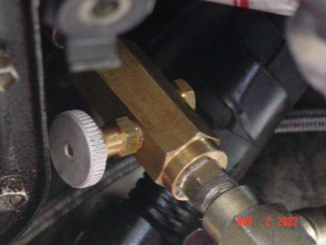
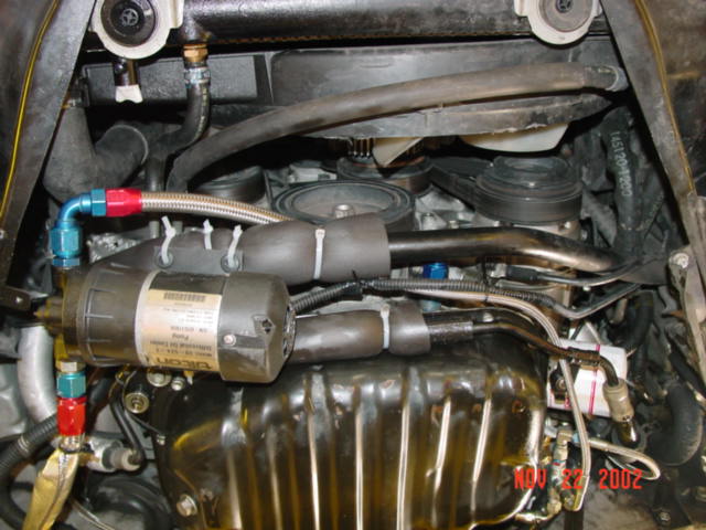
Due the location and height, oil return is unlike traditional method. The oil is obtained from the engine oil pressure gauge by using a T adapter along with a restrictor orifice bypass to control the oil flow to the turbos. The turbos are drain to a 8-AN stainless steel braided line, immediately the oil is be pick up by a Tilton self primed differential oil pump.
After the hot oil being drawn out of the turbos, it quickly pump the oil back to the oil pan. The rate of the inlet and outlet must be precisely accurate, otherwise your turbo will smoke or run dry. All the line being used are capable to withstand high temperature and pressure. All the connections are use Army/Navy (AN) standard fittings. With high temperature area, steel fittings are used. Low temperature area, aluminum fittings use for weight saving reasons.
The hardest part of this low turbo mount system is the oil. Too much oil or oil pressures going to the turbos will cause the turbo to smoke. Not enough oil, the turbo seals will break. Either way is not good news. Therefore, precise tuning of the oil flow is very important. After I destroyed 3 good condition turbos I finally realize that the proper oil flow is very important.
The oil being pump out of the turbos must be faster than the oil coming into the turbos, but not by much. This oil system utilized oil from the crank pressure. As the engine rev at higher rpm, so does the oil pressure. The increase of oil pressure will have higher oil flow. Currently, the system is tune to around 3000 rpm. For optimal oil cooler and lubrication, a small oil sump will be very useful.
I have a custom oil sump made with 1″ thick at one and 2″ at the other end with two 8-AN inlet and one 8-AN outlet. The oil sump is mounted between the two turbos and the Tilton oil pump pulls the oil out from the sump to the oil pan.
The oil sump is made specifically for low mount turbo/turbos. The sump solved all my oil problem. I also have a small opening on top of the oil sump for ventilation.
AIR INLET:
The air inlet from the turbos is unique in its own rights.
The inlet air travels under the car and jointing two 2″ mandrel bend tubes into one 3″ tube. The 3″ mandrel tube then lope up between the radiator and the engine. During this path, some intercooling is obtain. However, an intercooler can be place under the car. The compressor inlet of fresh air is place under the car. It uses two 2.5″ opening K&N high performance, low resistance air filter.
However, due to the low mount of these air filters, it is highly recommended to having a custom tube made up into the suspension area.
Recently, I have a local muffler shop made me two custom turbo inlet extension. These extensions are great with heavy rain. However, with those 2.25″ extension tubes, I noticed a slight restriction on the intake side.
During summer time, I will remove the extension tubes to achieve better flow.
INTAKE:
The intake uses a combinations of products.
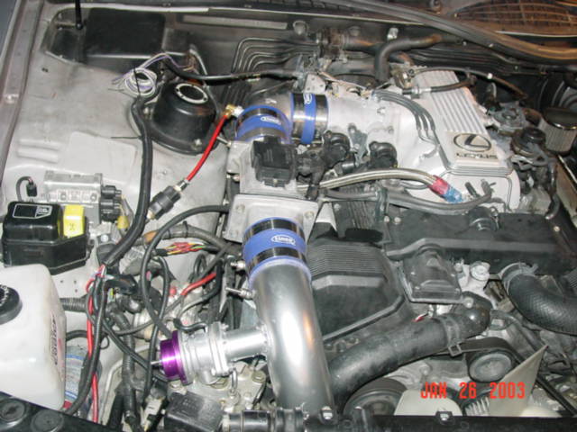
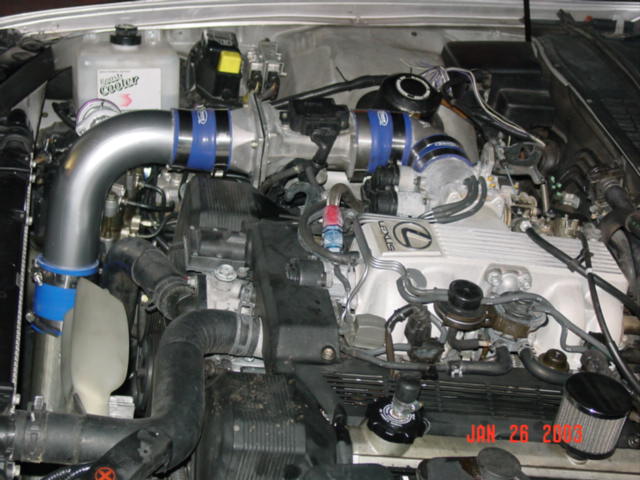
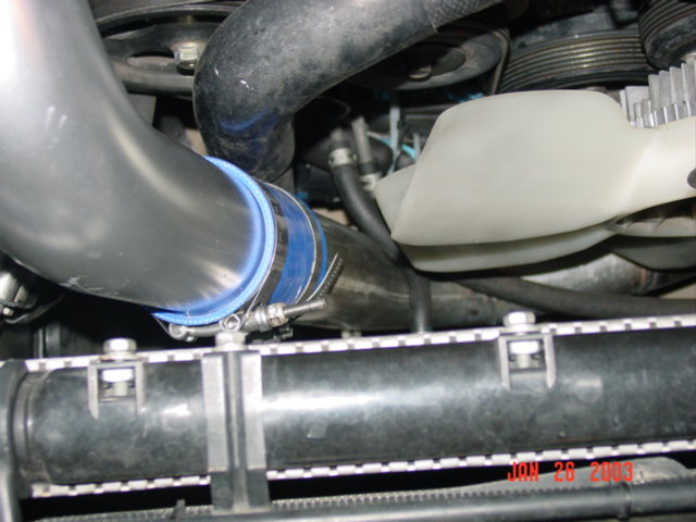
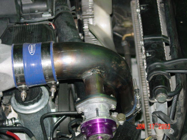
For example, Turbonetics short radius aluminum cast elbow is being used. Due to the tight space in the V8 engine bay, tight radius elbow is a favorable choice. The intake is connected with high quality silicon hoses by Hosetechniques along with heavy duty T-Bolt clamps.
All pipes have flare ends for strong connection. A Blow Off Valve (BOV) is being used. I choose Greddy Type S because is very quite.
Due to the location and the routing of the intake pipe, the fan cover need to be slightly modify. Running my turbo LS400 without a fan cover will cause excessive heat.
You can modify the OEM fan safety cover or get an aftermarket electric fan. 16″ electric fan is highly recommended.
INTERCOOLING:
Traditionally, a front or side mount air to air intercooler would be used. Due the limitation of the Lexus LS400 a small front mount intercooler was impossible.
Therefore, I used a Methanol/Water injection system. The methanol and water work as a median to cool the charged air through a boost sensitive activation.
Currently, its set to be activated at 7 psi.
For stage I, I am running 8 psi. Since I purchased this kit from above link, I have modified this kit heavily for safety sake. I replaced all cheap Home Depot plastic line to Stainless Steel Braided Lines and I also replaced those Push-In connectors to aluminum -AN fittings. I also completely replace the cheap plastic bottle with Jaz Fuel Cell. All connection are via metal/aluminum fittings.
I will increase boost to 9-11 psi in the near future with further fuel system upgrade.
Secondly, due to the location of the turbos, water cooling is not necessary. Since my turbos are air cooled, I have no change in my engine temperature.
The engine temperature is the same even with twin turbo. Due to the cool running turbos, turbo timer for cooling turbos down after ignition shutdown is not require. However, an air to air intercooler can be place under the car or some where by the fender.
After few days of assessment, I realized the horizontal and front mount would be very labor some and practical.
First, horizontal mount would have a ground clearance problem and front mount will be labor some due to the OEM AC fans and few other mounts. I have been reading about side mount turbos. The top two candidates of OEM intercooler would be Saab Turbo Intercooler or Eclipse 1st generation intercooler.
As for an update on intercooling, I purchased a 3″ x 6″ x 31″ intercooler which will be mounted under the bumper.
IGNITION:
The ignition and timing retardation will be control by MSD DIS 4. This unit is capable increasing ignition at the same it also control timing. Besides MSD DIS-4, Unichip can also control timing too.
Currently, I am running completely stock ignition.
FUEL:
Upgrade intake fuel is a must if more power is desired.
A High Pressure Walbro 255 L/H in-fuel pump is being used along with Aeromotive adjustable fuel pressure regulator (AFPR). If higher horse power is needed, 440 cc top feed injectors are highly recommended. Currently my stock fuel pressure is set to 39 psi. For Stage I (8 psi) stock fuel system is sufficient with a rising fuel pressure regulator to support up to 325 rwhp.
For greater horse power, larger injectors will be require. 400 rwhp would require 440cc and 500 rwhp would require 550cc. With larger injectors like 550cc a stand alone is highly recommended to control the large injectors during idle.
I have been looking at an Australian product call Wolf 3D Version 4. This stand alone computer is very affordable comparing to the rest of the stand alone computer on the market today. The Wolf 3D is about $700 U.S. Dollars.
CONTROL:
Currently, An Apexi Super AFC is being used as a piggy back computer along with OEM ECU. An Unichip is also a highly favorable choice. After playing around with my system, I finally realized with 8 psi, a piggyback is not necessary.
A basic adjustable rising fuel pressure regulator will do the job. Piggyback computer is necessary when bigger injectors are installed. Between 8-15 psi piggy back would work. More than 15 psi, a stand alone computer is high recommended or a combination of piggyback with rising fuel pressure regulator.
Here is my recommendation:
<8 psi – Rising Fuel Pressure Regulator with stock fuel system
8-15 psi – 440 cc with piggyback computer
>15 psi – Stand alone computer or a combination of RFPR and piggyback computer
However, I would recommended a stand alone computer for higher boost. The worst thing about boost engine is ill tuned.
PERFORMANCE:
Currently, car is dyno’ed at 324.5 rwhp and 324.7 rwtq at 8 psi without intercooler. I am sure that I can push it to 350 rwhp with more tuning and an intercooler. The stock 90 LS400 was dynoed at 172 rwhp. That is about 152 rwhp increase. That is about 20 rwhp per pound of boost. The car pulls very hard after 3000 rpm to redline. The dyno result on 01-30-03 was using stock fuel system. Please see dyno result.
I can not wait to see Stage II with estimated 500 rwhp.
I would like to take this sleeper to the track and find out what this beast can do in 0-60, 1/4 mile and so on. I would not be surprise to see low to mid 13 seconds with proper traction and driving skills. Currently, my spare engine is being build by a 36 years of experience engine builder.
He was one of the original engine builder for the legendary Carol Shelby in the 60’s. The new engine is getting custom JE Dish pistons with over bored .020″ along with O-ring head and groove block and ARP head studs and few other boost friendly goodies.
INSTALLATION:
If the kit ever sees the light of production, this kit will be truly bolt-on with few minor modifications to the exhaust and oil system.
I estimated the complete kit will take around 5-8 hours to complete. It will be a direct copy of my kit.
Twin Turbo Stage II Stage I Parts Installation Instruction
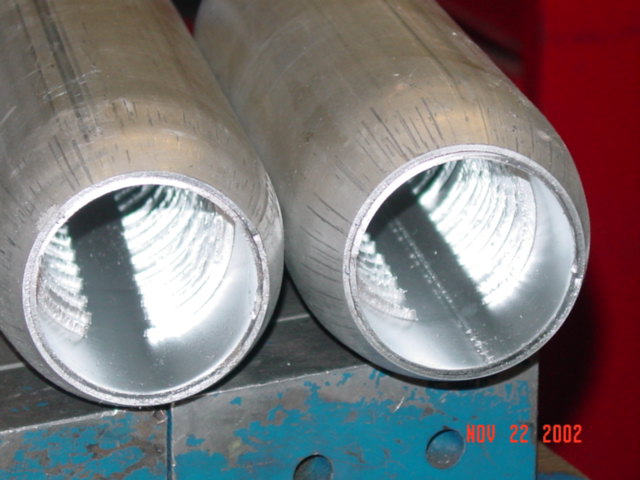
These are 3″ resonator help quite exhaust noise. These are high flow
resonators. They are louder than stock
These are two 12″ long 3″ diameter straight resonators. My car have
total of 4 resonators.
High quality hoses and T-bolt clamps are being used. The intake pipe
will be chrome soon.
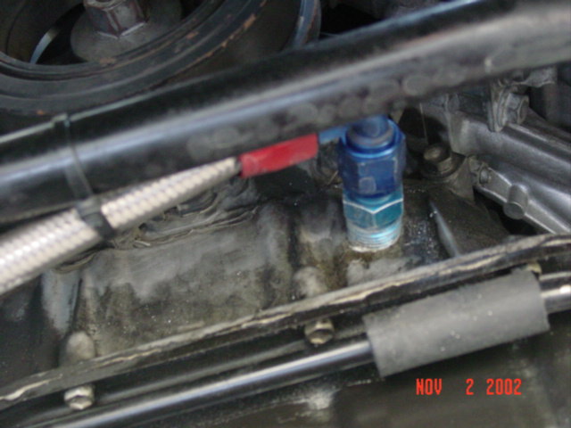
This is the turbo inlet flange along with braided stainless steel line. This
is no longer use. Its being replace with 2″ pipe
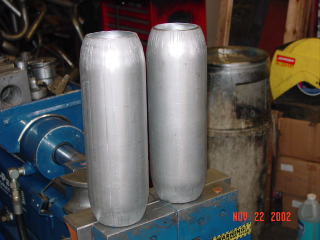
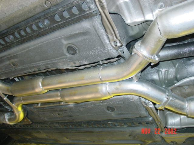
The picture shows two 3″ straight pipe before the primary resonators were installed.
This is the secondary resonator: its 18″ long with 3″ diameter.
This picture show both primary and secondary resonators installed with protected spray.
In this setup, the car idle much smoother like OEM. MAF gets smooth air
flow.
This is the driver side turbo. Notice the blue silicon hose for filter connection.
This is the passenger side turbo along with oil drainage line.
Close up on driver side turbo.
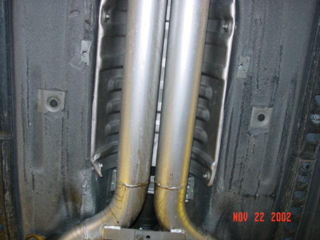
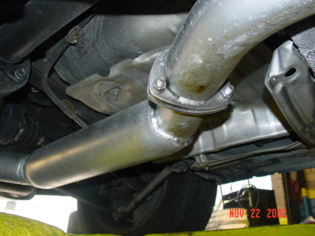
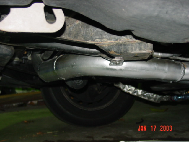
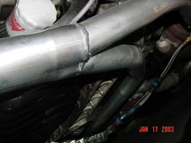
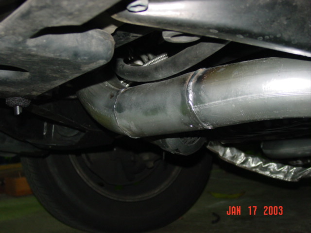
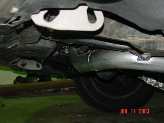
The down pipes (DP) are 3″ mandrel bend steel pipe.
Side view of right turbo along with 2″ mandrel bend tubes.
Close up left turbo. These turbos spool up very quick. 8 psi at
around 2600 rpm.
Thermotec heat wrap and tie.
Rear view of left turbo along with Turbonetics actuator.
The is the first oil drain path. Later it was changed to center T-Drain.
This is a tight turn of the left turbo. Notice the protective wrap and straps.
Oil drain line of the right turbo and actuator.
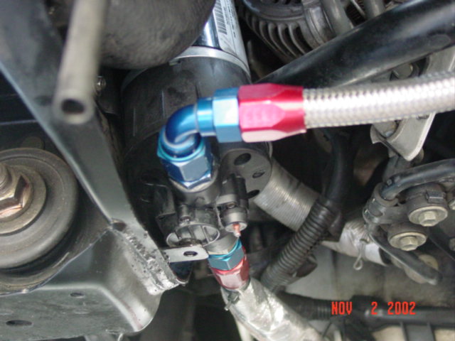
The turbo outlet is connected to the braided line. All connections use heavy duty T-Bolt clamps.
Oil drain line from turbos to the oil pump.
Other view of drainage line along with thermal wraps.
This is OEM Nissan Skyline actuator. The bracket fit perfectly. The right
turbo actuator was just bolt-on. Stock actuators for 8 psi..
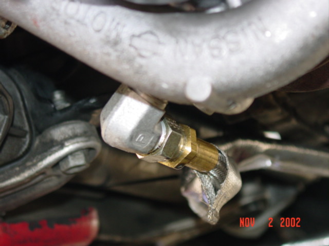
You are seeing the oil needle restrictor along with T-connection.
Crank oil pressure is being to supply oil to the turbos.
Excellent view on the AN fitting.
Side view of the driver side turbo with K&N filter.
Two 2″ mandrel bend pipes are joint in a 3″ Y-pipe. Very
clean setup.
Top view of the custom intake along with two inlet braided line and blow off valve.
The OEM air filter is where the methanol/water injection is located.
A clear picture of Greddy Type S BOV. Its not loud.
Rear view of stainless steel MagnaFlow muffler. The Magnaflow muffler has both 3″ inlet and outlet.
Beautiful picture of the Y-pipe.
This system is none intercooled, but the pipping will provide some
intercooling effect.
These are custom adapter that connect to the OEM headers and turbos.
This is the driver side turbo with 3″ down pipe and thermal wrap.
Picture of the two DP along with Greddy BOV
That is my superchaged 15 psi with built motor and 6 speed.
This is a short radius cast aluminum elbow from Turbonetics. Pipes are connected with heavy duty T-Bolts clamps.
Alcohol/Water injection system
Side view of the intake along with the removal of fan protector.
More pictures on inlet pipe going up into the throttle body.
This is my gauge pod. I am using my glove compartment to hide all the gauges. SLEEPER!
Rear view of dual mufflers. This is how it looks like from a M5, CK55 AMG and Jag driver.
Left rear view of Magnaflow and 3.25″ stainless steel tip.
Right muffler. Polished finish
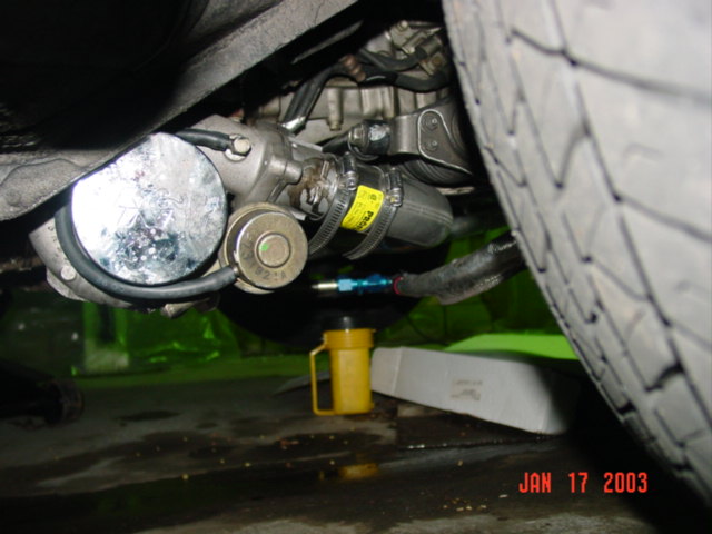
Adjustable needle valve to help oil restriction
New location of Tilton Differential oil pump. This mounting location help to reduce vibration.
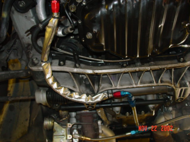
This is the return oil to the oil pan via a braided line 8-AN
Close up of Tilton oil pump and lines
This is the new oil lines. Two to the turbos and one bypass back to the oil pan.
New drainage path, notice protective sleeve.
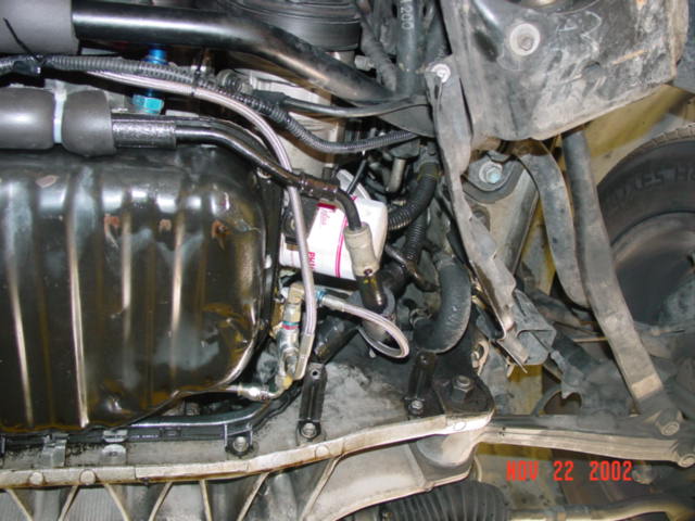
General under car view of oil pump and lines. The heart of the oil
system is the pump.
Oil drain line from turbo
You might also find this video interesting and helpful.
Do you have any questions? If so, please head over to the forums to get a quick answer or share your experience!
Cash App (user: $lextremeparts).
This is a freelance site with no support by huge companies.
I have been doing most of the R&D and technical write-ups by
myself with my personal money and literally thousands of hours of my time. I have taken extra steps to
demonstrate in details how things are done. Currently I am
one of the few people doing Lexus V8 research and performance
enhancement. This effort comes from my personal love for
this wonderful engine. Most of the modifications are from
trial and error. There's no cookbook for 1UZFE
mods and its unknown territory for much of supercharger performance.
The parts, labor, web development and site hosting are
100% paid from my personal hobby money. If you feel my efforts help you
in any form, please do not hesitate to donate any amount of money
to support this site. You have no idea how much I and the entire Lexus and Toyota community appreciate it!
3 thoughts on “Lexus LS400 1UZ-FE Turbo Kit”
ive just stumbled across this now and its 2019 but its still 100% relevant and pretty much exactly what i was looking for. thanks heaps for taking the time to write this up.
Im contemplating going to a ls400 earlier year have owned several high powered cars mostly Toyota and not long ago bought a audi s7 , well ill never own another audi omg. Im a toyota man at heart. And I wanna go down the turbo road ls400 1uz . I loke the detail in ur storie and wld b going to do something similar to urs . Realy loke the twin turbo vq set up tho low mount has me worried due to placement. Ill b using someone ur info so thanks. Keep boosting ls400
.jpg)
.jpg)
.jpg)
.jpg)
.jpg)
.jpg)
.jpg)
.jpg)
.jpg)
.jpg)
.jpg)

.jpg)
.jpg)
.jpg)
.jpg)
.jpg)
.jpg)
.jpg)
.jpg)
.jpg)

.jpg)
.jpg)
.jpg)
.jpg)


.jpg)


ive just stumbled across this now and its 2019 but its still 100% relevant and pretty much exactly what i was looking for. thanks heaps for taking the time to write this up.
Thank you for all of your research
Im contemplating going to a ls400 earlier year have owned several high powered cars mostly Toyota and not long ago bought a audi s7 , well ill never own another audi omg. Im a toyota man at heart. And I wanna go down the turbo road ls400 1uz . I loke the detail in ur storie and wld b going to do something similar to urs . Realy loke the twin turbo vq set up tho low mount has me worried due to placement. Ill b using someone ur info so thanks. Keep boosting ls400