Intercooling an Opcon twin screw - options

The 1UZFE EGR Delete Kit is available for sale here.

Zuffen

Super Moderator
Staff member
Messages
5,631
Location
Sydney, Australia
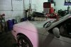
I'm about to rebuild my supercharged engine.

I've decided the water injection wasn't offering the temp control I needed at 22.5psi.

I have 3 options:

1. Fit a W2A intercooler into the manifold.

2. Fit an external W2A intercooler.

3. Fit an FMIC.

Pros:

1. They're available and a little machining and it fits.

2. I can get better cooling and improve the air entry into the manifold.

3. It's easy reliable and I have an intercooler hanging around.

Cons:

1. Has he complication and weight of a pump, water plumbing, pump and an additional radiator.

2. See above and add building the box and supporting the intercooler somewher in a very cramped engine bay.

3. I still need the box but room is available and a little plumbing isn't too hard.

I lean toward option 3.

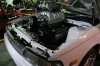
My reasoning is I can fit the intercooler in front of the radiator and plumb it up fairly easily. Core size is 600mm x 300mm with a 2 3/4" inlet and 2 1/2" outlet. All the claculations say it will support up to 700 HP.

I happen to have the intercooler (so I can save the cost of a new one) which came off a Shelby Elenor (Gone in 60 Seconds) Mustang that was making well over 600HP at the wheels.

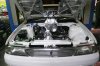
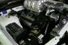
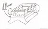
To get the air out I can build an aluminium box to go under the supercharger that is splt diagonally (top rear to bottom front) so I can take the air out from the supercharger, through the intercooler, and back to the rear of the "box" which would discharge it into the manifold.

The existing setup has poor air distribution (which may have contributed to the blown h/g) and retunring the air to the centre of the rear of the manifold would give it far better distribution.

If I ran air to air I would use the existing water injection to spray the intercooler core with straight water. This would leave me a lot of unused methanol to get rid of but I'm sure I can find a use for it.


I'm after any and all comments on my options.

I plan on this being the last 1UZ build I do for a few years so I want to get it right.

What do you think?
 
Imo run a bigger pulley on blower, slow it down some..
How far is your nearest E85 fuel station ??
Each cylinder can be tuned individually..
I have intercooler that size on my Ford it sure flows atleast 700 h.p..
 
Rod, first I've had no experience with W2A setups since leaving Caterpillar years ago. I've only used A2A since then, but at Cat, when we required the highest level of intercooling possible for our engines' highest output ratings, it had to be A2A. So I'm a bit biased about these setups.

I would use the A2A intercooler that you already have, plus I would keep the M/W injection setup for the motor, but experiment with different ratios of M/W. Contrary to popular notions about 50/50 mixes being most efficient, I found on the dyno, that straight methanol cooled my charge air much better than any mix.

I would inject the M/W or straight meth in at least two, and possibly three locations:

1) Presupercharger: this will help keep the supercharger cool under high boost. We've both now seen that our Opcons get extremely hot under sustained high boost.

2) From the bottom of the Richwood manifold, straight up, directly into the incoming discharge air from the charger.

3) Possibly a third nozzle mounted in the center of the rear wall of the manifold, looking forward.

Under dyno testing, it wasn't until I had nozzles in both #2 & #3 locations that my charge air temps dropped significantly. Unfortunately I had to sacrifice the nozzle I was running in location #1 to put in #3, so my Opcon ran extremely hot afterward. I'll definitely be running all three nozzles in the future, and I would guess I'll be pumping upwards of a litre per minute into the motor under high boost, however realistically, in a car, it's going to be rather difficult to stay in boost for more than 5-10 seconds at a time.

Offtopic a bit from the thread title, and it may sound obvious, but ensure your rebuilder puts a proper crosshatch pattern on the cylinder walls and does it with the proper honing equipment to get the correct surface finish. None of this "quickie cleanup" stuff with abrasive balls in an electric drill. New rings have to have the right surface profile and crosshatch to seat. If not, they'll never seat and then you really will want to set the motor on fire.

Since you'll be in the shortblock anyway, you "might" want to consider installing a set of oil squirters from the 2UZ motors. They're dead simple to install, and if Toyota and nearly every other major OEM go to the extra trouble to install them on their boosted motors, there must be a good reason. Either David or I can get them for you if you don't have good access to Toyota parts there.

I'm a big believer in coatings, and would have the piston crowns ceramic coated, and their skirts, and all the bearing shells moly coated. Again, it's just good insurance.

I'd be most concerned about the shearing of that cam drive pin, and the possibility of it happening again. I know that Erol has experienced this as well, and has installed additional drive pins for his setups, so it may not be a bad idea for us to do the same.

As difficult as it is to get that motor in & out of your vehicle, there's no way I'd reinstall it until it was broken in and sorted out on an engine dyno. It's a substantial extra cost, but I just look at engine dynoing as being part of the cost of rebuilding motors now.

For the initial breakin, I'd use a straight 30w dino oil.

And as XR8TT said, for running on pump gas, you'll want to turn the boost down. Either run a bigger pulley on the charger, or try one of those dual port actuators for your bypass valve so you can control boost. I have one on mine, but to be honest, haven't tested it yet.
 
Hmm perhaps too many beers for this advice but here's my take.

If you want air/water then a laminova setup is the go. Results i have seen are extremely impressive. It would suit your setup perfectly but pretty serious dollars.

air/air is definitely viable and Neil here in Canberra is doing the splitter manifold so straight up there's an option. Knowing your luck with 'all talk and no deliver' workshops i would also highly recommend my machinist. He's a perfectionist to the point of painful, extremely skilled but a joy to work with and will deliver more than you want.

As you say, this is a good opportunity to get better air distribution. A better bang for buck option and if you have the room for plumbing then i'd say this is probably the way to go.

Keep the WI, at least for now. Tuning will reveal the need and/or benefit.

Just a comment on John's observation. It's not all about intake temps John. Yup alcohol will do this job best but where water comes into it's own is it's high latent heat point which absorbs alot of the energy in the combustion burn. The actual chemistry going on is a bit of a black art but essentially WI slows the burn and effectively increases torque as more energy goes into driving the crank and less out the exhaust as heat. It's also great for controlling det and keeps you engine insides nice and shiney. I think my stock engine is testament to the benefits of 50:50 water/alcolol.

Lastly, fuel. E85 has to be the go......yet to try myself but i'm getting there. My tuner says yes yes yes. He has had great results powerwise and the cooler running temps can only be a plus.

That's i can think of now but happy to expand on myn initial thoughts and/or help twist your arm one way or the other :)

F
 
If you have plenty of room on top of your engine which I think you do, I would go FMIC. A spacer manifold wouldn't be too hard to make up and plumbing would be easy to the front with a few 90 bends. Would probably add about 50 - 60mm to the SC height.

I have attached my mad sketch, I have been thinking to do something similar myself, although height is an issue for me without mods to the scoop.

I don't think a W2A cooler inside the manifold is anywhere big enough to get rid of the heat. The physics don't really work out due to the surface area of the core, the air flow and contact time. Laminova cores would be different but lots of messing around and expensive.

A diffuser plate could be used to even out the air flow back into the manifold. Easy to slide out and play with port size etc.
 

Attachments

  • P1000829.jpg
    P1000829.jpg
    229.4 KB · Views: 14
  • P1000830.jpg
    P1000830.jpg
    214.7 KB · Views: 13
  • P1000831.jpg
    P1000831.jpg
    243.9 KB · Views: 13
  • P1000832.jpg
    P1000832.jpg
    248.1 KB · Views: 13
Cobber,

I'm looking at a remote W2A intercooler with 3 1/2" inlet and outlet.

The W2A has the benefit of being able to maintain cooling over a long period of time as against a FMIC which will heat up if you keep on the gas long enough. Plus it fits much easier!

My box would be around 3" with eliptical inlet and outlet.

I'd plan on feeding the air back into it from the rear as I feel this would give better distribution.
 
Cobber,

Very simillar.

I plan on keeping the added height down to 95mm which will accomodate 31/2" pipes with a few millimetres of alloy left over.

This will be a very tight fit under the bonnet.

I'm not sure if I should insulate the outlet pipe from the manifold where it's inside the maniflod as it will/may heat up the already coolled charge air.

Not sure what I could use and be 100% happy it wouldnt' flake of and pass through the engine.

I could perhaps add a small air space around it so it has to heat up two pipes and the air.

Alternatively I could ceramic coat it as well.

I'm open to thoughts/comments/ideas.
 
I'm not sure I have the right end of the mental picture.

A layer of 5mm E glass needle mat, wrap it round like a bandage and then wrap it in a layer exhaust wrap.

No pretty but an extremely effective insulator.
 
Just re read this again and you want to insulate the divider plate that sits inside the manifold that separates the air from the supercharger out to the cooler and where it comes back in right?

You mention an air gap between the two plates, well this is where you put the insulation material (E Glass). You wrap the pipe from the cooler to where it goes back in to the manifold. The pipe from the manifold to the cooler should not be wrapped.

My side pipes are packed with E Glass and I can put my hand on them no problem straight after driving.
 
Had an interesting discussion with Andrew from Richwood last night.

A few facts:

1. Peter Perano (I think that's the spelling) runs 45psi through his stock/untouched Richwood manifold

2. Peter makes an estimated 1,800fwhp on a stock block and crank.

3. He runs 7 second 1/4 mile passes.

4. He also has killer head and bottom end studs in it.

Andrew has made one splitter box, as I wanted and almost exactly what Andy drew, for Neil from Rush Imports.

I've asked Andrew for a price on his billet box as it will always be more acurate than anything I can have fabricated.

I spent Monday on the die grinder and all I have left to do is balane the size of the new ports with each other. I'm looking for 52mm wide x 33mm high runers as these have almost the exact crossectional dimension as the inlet ports in the head.

Hopefully after another day on the ports they will be tolerably close to each other.
 
Not sure what happened to my previous post in this thread but here is the picture of the air divider manifold I drew up for those that have asked.

Diffuser plate can be used to even out any air flow issues.

Any progress on this project Rod?
 

Attachments

  • FMIC Manifold.jpg
    FMIC Manifold.jpg
    34 KB · Views: 6
That's essentially what I'm having machined up at the moment.

The outlet uses a short fishmouthed pipe from the divider plate and the inlet uses a long one (as long as the manifold) and the divider is split from the top to bottom across from inlet top to outlet bottom.

The outlet in my case is toward the front as that is where the Opcon discharges its air.


Top