You are using an out of date browser. It may not display this or other websites correctly.
You should upgrade or use an alternative browser.
You should upgrade or use an alternative browser.
1uz / Nissan 6 speed Mercedes 190e swap
- Thread starter 190-v8
- Start date
The 1UZFE EGR Delete Kit is available for sale here.

I will have a look at the cam cover when the motor is out again. The area that it interferes with is going to be quite easy to modify though.
As for the cross member vs Sump cutting.... I am going to cut into the cross member and then weld in a vertical plate formed to the missing profile. Once everything fits I am going to weld in the the steering rack plate which will beef it up considerably.

One option with the cam cover is to cut the corner off the cover.
There is quite a lot of room in the rear corner.
Plenty of people have trimmed their cam covers and welded apiece back in.
I'd also be more inclined to mod the sump oil pan to fit rather than take anything out of the cross-member.
There is quite a lot of room in the rear corner.
Plenty of people have trimmed their cam covers and welded apiece back in.
I'd also be more inclined to mod the sump oil pan to fit rather than take anything out of the cross-member.
One option with the cam cover is to cut the corner off the cover.
There is quite a lot of room in the rear corner.
Plenty of people have trimmed their cam covers and welded apiece back in.
I'd also be more inclined to mod the sump oil pan to fit rather than take anything out of the cross-member.
I will have a look at the cam cover when the motor is out again. The area that it interferes with is going to be quite easy to modify though.
As for the cross member vs Sump cutting.... I am going to cut into the cross member and then weld in a vertical plate formed to the missing profile. Once everything fits I am going to weld in the the steering rack plate which will beef it up considerably.
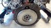
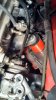
Flywheel bolted on torqued with new ARP bolts.
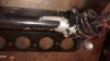
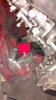
I cut the "offending" bolt bosses off the steering rack and smoothed it a bit. This combined with the editing the front of the cross member should allow the motor to sit in the right spot. Also, I am hoping that since the rack is a bit higher than where others have placed theirs I might be able to get away without clearancing the the top of the lower control arms....we will see fairly shortly.
I cut the "offending" bolt bosses off the steering rack and smoothed it a bit. This combined with the editing the front of the cross member should allow the motor to sit in the right spot. Also, I am hoping that since the rack is a bit higher than where others have placed theirs I might be able to get away without clearancing the the top of the lower control arms....we will see fairly shortly.
Attachments
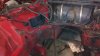
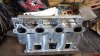
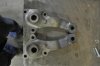
The 1uz stock mount location is very close to the same width as the holes in the factory MB cross member.... But on the cross member they are not the same height side to side or flat...at least on a 2.3l equipped car. I am replacing that area with 3mm thick flat plates sunken down to be level.
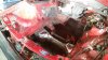
Before I started on the mounts I cut open the side firewall to allow better head clearance - I will button this up after I have the motor in place and can really see what it needs properly.
I cut the tops off the stock cross member - the drivers side is higher by about 5/8" approximately so it had to be cut back toward the center more than the other side.
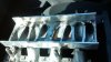
I kept cutting basically until I could get a piece of flat steel to sit across the tops and be level. Once that was done I cut the basic shape out of the 3mm plate and cut 2 slots in for the motor mount bolts. The slots will allow me to adjust front to back motor placement for the best fit. When I had the motor in it looked like it could go back about 1" but hard to tell until the trans is bolted up as well and clearing the firewall...better safe than sorry and I have about 2" of movement available.
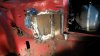
Once I was happy with the basic profile and the position I started to tack the piece in and then weld the areas that touched the stock cross member.
The reason I left the center of the plate intact was so that I could easily check and make sure both sides stayed flat and level. Now that the plates were substantially welded in I cut the center out. They are perfectly flat and level...even though it does not really look like it in this pic.
Next up I am going to box in the open sides and then cut back the center of the cross member.
Before I started on the mounts I cut open the side firewall to allow better head clearance - I will button this up after I have the motor in place and can really see what it needs properly.
I cut the tops off the stock cross member - the drivers side is higher by about 5/8" approximately so it had to be cut back toward the center more than the other side.
I kept cutting basically until I could get a piece of flat steel to sit across the tops and be level. Once that was done I cut the basic shape out of the 3mm plate and cut 2 slots in for the motor mount bolts. The slots will allow me to adjust front to back motor placement for the best fit. When I had the motor in it looked like it could go back about 1" but hard to tell until the trans is bolted up as well and clearing the firewall...better safe than sorry and I have about 2" of movement available.
Once I was happy with the basic profile and the position I started to tack the piece in and then weld the areas that touched the stock cross member.
The reason I left the center of the plate intact was so that I could easily check and make sure both sides stayed flat and level. Now that the plates were substantially welded in I cut the center out. They are perfectly flat and level...even though it does not really look like it in this pic.
Next up I am going to box in the open sides and then cut back the center of the cross member.
Attachments
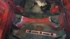
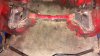
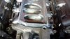
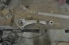
Some more progress...
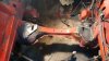
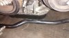
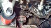
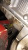
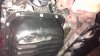
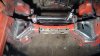
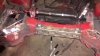
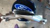
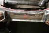
Motor mounts are done, the cross member has got a big notch cut into it temporarily to clear the sump (will finish that soon) with a pipe section welded inside to reinforce, the front sway bar clears the sump and the steering rack clears the pan too")
Motor mounts are done, the cross member has got a big notch cut into it temporarily to clear the sump (will finish that soon) with a pipe section welded inside to reinforce, the front sway bar clears the sump and the steering rack clears the pan too
Attachments
-
 sway bar clears.jpg149.8 KB · Views: 13
 -
 rack clears.jpg167.6 KB · Views: 13
 -
 sump clearance rear.jpg112.2 KB · Views: 15
 -
 under sump.jpg134.2 KB · Views: 16
 -
 drivers side mount.jpg115.8 KB · Views: 14
 -
 pass side mount.jpg103.4 KB · Views: 14
 -
 pipe in.jpg109.3 KB · Views: 16
 -
 pipe section in.jpg164.7 KB · Views: 15
 -
 yikes.jpg145.9 KB · Views: 16
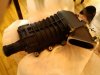
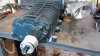
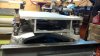
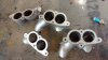
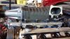
Been busy with other things as of late but got a bit of time to work on the manifold set-up that I was inspired to make from another poster on here . I bolted the manifold to a flat steel jig to keep it flat when it is welded.
The port opening have been smoothed pretty well - ready to have the plenum welded onto the shaved manifold.
The supercharger mount plate will be welded on from upside down after the plenum is welded... then the end caps will be welded on last. Once all the welding is done I will have it lightly milled to ensure it is flat on the top and cut the openings for the supercharger inlet.
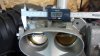
I found a factory GT500 shelby throttle body for a good deal and it fits without modification so looks like that is the one I will use - twin 57mm butterflies should be just fine for flow....I just have to convert it from drive by wire to throttle cable.
I also removed the 2.6" diam pulley that would have given way too much boost to start off with - about 14-15psi with the stock crank pulley I think. It also placed the grooved belt area too far back for this application. I can use the pulley originally designed for the Ford Lightning pick-ups to bring the boost down to about 9psi and place the ribs in a more forward location.
. I bolted the manifold to a flat steel jig to keep it flat when it is welded.The port opening have been smoothed pretty well - ready to have the plenum welded onto the shaved manifold.
The supercharger mount plate will be welded on from upside down after the plenum is welded... then the end caps will be welded on last. Once all the welding is done I will have it lightly milled to ensure it is flat on the top and cut the openings for the supercharger inlet.
I found a factory GT500 shelby throttle body for a good deal and it fits without modification so looks like that is the one I will use - twin 57mm butterflies should be just fine for flow....I just have to convert it from drive by wire to throttle cable.
I also removed the 2.6" diam pulley that would have given way too much boost to start off with - about 14-15psi with the stock crank pulley I think. It also placed the grooved belt area too far back for this application. I can use the pulley originally designed for the Ford Lightning pick-ups to bring the boost down to about 9psi and place the ribs in a more forward location.
Attachments
Been pretty slow with the progress as of late....
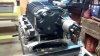
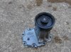
I did trim the front of the plenum on an angle to clear the water jacket and bent a front "plenum wall".
I found a cheap M112 snout on Ebay and am going to use that on the M122 to space the SC back more. Pretty happy about finding one...not so easy to buy them separately I have found out.....
I did trim the front of the plenum on an angle to clear the water jacket and bent a front "plenum wall".
I found a cheap M112 snout on Ebay and am going to use that on the M122 to space the SC back more. Pretty happy about finding one...not so easy to buy them separately I have found out.....
Attachments
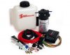
Another piece of the puzzle sorted last night....I got a great deal on a Snow Performance stage II water/meth injection kit! This will be used to cool the intake charge instead of an intercooler.
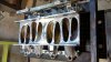
Just about finished the manifold....A bit uglier than I would have liked welding wise...but should be strong enough and air tight.
Just about finished the manifold....A bit uglier than I would have liked welding wise...but should be strong enough and air tight.
Attachments
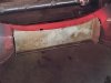
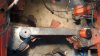
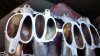
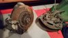
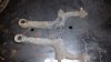
I recently bought some 300e spindles, calipers, vented discs and steering arms. The stock 190e front brakes brakes have 10.2" solid discs and these direct bolt-ons are 11.5" and vented with larger calipers and pads. These are basically the same brakes that MB put on the Cosworth 16v 190e cars for racing.
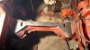
I need to cut the steer arms down 1.25" so that they will work properly with the Jetta rack. This is what they look like before editing. I will cut them down and jig them up but won't be doing the welding myself. It is too important that a pro does this and I have contacted a long time well regarded local race car fab shop to TIG them back together for me. It will be done similar to these BMW arms that were shortened:
It was sooo lucky I managed to contact the owner of this V8 1090e and that he shared all of his measurements and engineering regarding the R&P swap! My interpretation is slightly different but what a great starting point from a known sorted car that works well. His has a 400+hp SBF/5 speed in it and is apparently a terror on track.
Attachments
Trollburger
New Member
Really impressive work. My project has been delayed for a long time due to other customer's project(to earn money!) like M104 3.2 on 190E. Your Jetta R&P application looks way better and simper than my wider W210 R&P which screws suspension geometry and LCA also needs to be cut.
Thanks for the positive feedback Trollburger!
This project has been "paused" for a while while we move and renovate our new (old) place. I have also been busy building cnc plasma tables as well. I am hoping to get back to the benz project in the next month or so.
www.hotrodfab.com
This project has been "paused" for a while while we move and renovate our new (old) place. I have also been busy building cnc plasma tables as well. I am hoping to get back to the benz project in the next month or so.
www.hotrodfab.com
Similar threads
- Replies
- 1
- Views
- 693
- Replies
- 3
- Views
- 825