I wrote this for elsewhere, but thought you guys could use it.
Background:
Automatics are awesome. While the older automatics do a phenomenal job matching the shift pattern to the powerband when accelerating. You can find yourself wishing for a different gear at part throttle. Say flying through the entry of afew corners.
Low does fine for first gear. 2 can still downshift to 1st, and there is no way to hold third, or fourth. Annoying... So let's make this thing our bitch without spending hundreds on a transmission controller!
Theory:
If we can control the shift pattern. Our cars will have sex with us.
Instructions:
We'll need about $15-$20usd in basic electronic hardware.

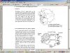
Shift Solenoid 1 = E10 (S1)
Shift Solenoid 2 = E9 (S2)
Torque Convertor Lock-Up Solenoid = E8 (SL)
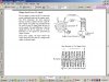
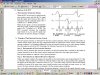
Here is the shift pattern for S1 & S2 that derive the four gear ratios of the A540e transmission:

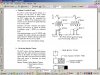
What we are going to do is change the wiring to the shift solenoids the control the gear selection (in drive) of the transmission. We are going to re-route the stock wiring through a DPDT relay (AKA Primary relay). When the relay is normally closed, they will pass the ECU signal as normal. When they are opened (powered). The relay will switch the circuit through a 15ohm 25 watt resistor to chassis ground. This will satisfy the stock ECU's desire to always see a 15ohm load from the solenoids.
From this point. The SPST relays (Secondary relays) will be spliced into the solenoid wiring AFTER the primary relay. When the relay is in the closed position, there will be no current to the solenoid. When the relay is tripped, it will supply the solenoid with current from a 12v supply from the common rail.
****************************************
For the torque convertor, we will splice one SPST relay(primary relay) onto the SL torque convertor lock-up. Normally Closed will pass the ECU signal as normal. Open will send the ECU's current through the remaining 15ohm 25watt resistor on it's way to chassis ground. Our last SPST relay (secondary relay) will connect as the others. Spliced in AFTER the previous relay. Open will connect a 12v supply from the common rail to the solenoid.
****************************************
I suggest the torque convertor secondary relay to be connected through a normal push-button switch, or toggle switch.
****************************************

****************************************
The primary relay's coil supply should be put together & routed to the switch area. Route a wire from each of your secondary relay's coil to your switch area. You should have four wires. A line from S1, S2, SL, and the two first relays.
****************************************
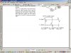
Now for wiring our shift circuit!
Our 6-pole switch has 6 positions, and 14 connections. 2 connections will stand in the middle (Connect both of these together to a suitable 12v power supply.)
The remaining 12 connectors ring around the switch.
This is a double pole switch, so on any of our 6 positions, it will connect to two of the connectors. (Specifically, opposite sides.)
You can wire, to any way you wish. I chose:
Position 1 = Drive (normal ECU)
Position 2 = 1st gear
Position 3 = 2nd gear
Position 4 = 3rd gear
Position 5 = 4th gear
Position 6 = Drive (normal ECU)
To do this, from your starting position:
****************************************

****************************************
Ta-da! We now have the ability to successfully bypass the stock control whenever we want, and select any gear we want (Including normal Automatic features), and at the same time controlling the torque converter lock-up how we want.
Anytime the 6-pole switch is in positions 2-5. The Primary relays will swap the ECU to see ground. And the secondary shift solenoids will be operated in the manner of gear selection. The Torque convertor will operate at-will of your switch.
****************************************
Background:
Automatics are awesome. While the older automatics do a phenomenal job matching the shift pattern to the powerband when accelerating. You can find yourself wishing for a different gear at part throttle. Say flying through the entry of afew corners.
Low does fine for first gear. 2 can still downshift to 1st, and there is no way to hold third, or fourth. Annoying... So let's make this thing our bitch without spending hundreds on a transmission controller!
Theory:
If we can control the shift pattern. Our cars will have sex with us.
Instructions:
We'll need about $15-$20usd in basic electronic hardware.
- 1 6-position, double pole rotary switch
- 1 push button switch
- 1 DPDT Relay
- 3 15ohm 25 watt resistors
- 4 SPST Relays
- Around 10-15' of wiring (I used 20gauge)
Shift Solenoid 1 = E10 (S1)
Shift Solenoid 2 = E9 (S2)
Torque Convertor Lock-Up Solenoid = E8 (SL)
Here is the shift pattern for S1 & S2 that derive the four gear ratios of the A540e transmission:
What we are going to do is change the wiring to the shift solenoids the control the gear selection (in drive) of the transmission. We are going to re-route the stock wiring through a DPDT relay (AKA Primary relay). When the relay is normally closed, they will pass the ECU signal as normal. When they are opened (powered). The relay will switch the circuit through a 15ohm 25 watt resistor to chassis ground. This will satisfy the stock ECU's desire to always see a 15ohm load from the solenoids.
From this point. The SPST relays (Secondary relays) will be spliced into the solenoid wiring AFTER the primary relay. When the relay is in the closed position, there will be no current to the solenoid. When the relay is tripped, it will supply the solenoid with current from a 12v supply from the common rail.
****************************************
For the torque convertor, we will splice one SPST relay(primary relay) onto the SL torque convertor lock-up. Normally Closed will pass the ECU signal as normal. Open will send the ECU's current through the remaining 15ohm 25watt resistor on it's way to chassis ground. Our last SPST relay (secondary relay) will connect as the others. Spliced in AFTER the previous relay. Open will connect a 12v supply from the common rail to the solenoid.
****************************************
I suggest the torque convertor secondary relay to be connected through a normal push-button switch, or toggle switch.
****************************************
****************************************
The primary relay's coil supply should be put together & routed to the switch area. Route a wire from each of your secondary relay's coil to your switch area. You should have four wires. A line from S1, S2, SL, and the two first relays.
****************************************
Now for wiring our shift circuit!
Our 6-pole switch has 6 positions, and 14 connections. 2 connections will stand in the middle (Connect both of these together to a suitable 12v power supply.)
The remaining 12 connectors ring around the switch.
This is a double pole switch, so on any of our 6 positions, it will connect to two of the connectors. (Specifically, opposite sides.)
You can wire, to any way you wish. I chose:
Position 1 = Drive (normal ECU)
Position 2 = 1st gear
Position 3 = 2nd gear
Position 4 = 3rd gear
Position 5 = 4th gear
Position 6 = Drive (normal ECU)
To do this, from your starting position:
- Empty, opposite empty
- Connect to S1 (solenoid 1) and first relays, opposite empty
- Connect to S1 and first relays, opposite connect to S2 (solenoid 2)
- Connect to first relays, opposite connect to S2
- Connect to first relays, opposite empty
- Empty, opposite empty
****************************************
****************************************
Ta-da! We now have the ability to successfully bypass the stock control whenever we want, and select any gear we want (Including normal Automatic features), and at the same time controlling the torque converter lock-up how we want.
Anytime the 6-pole switch is in positions 2-5. The Primary relays will swap the ECU to see ground. And the secondary shift solenoids will be operated in the manner of gear selection. The Torque convertor will operate at-will of your switch.
****************************************