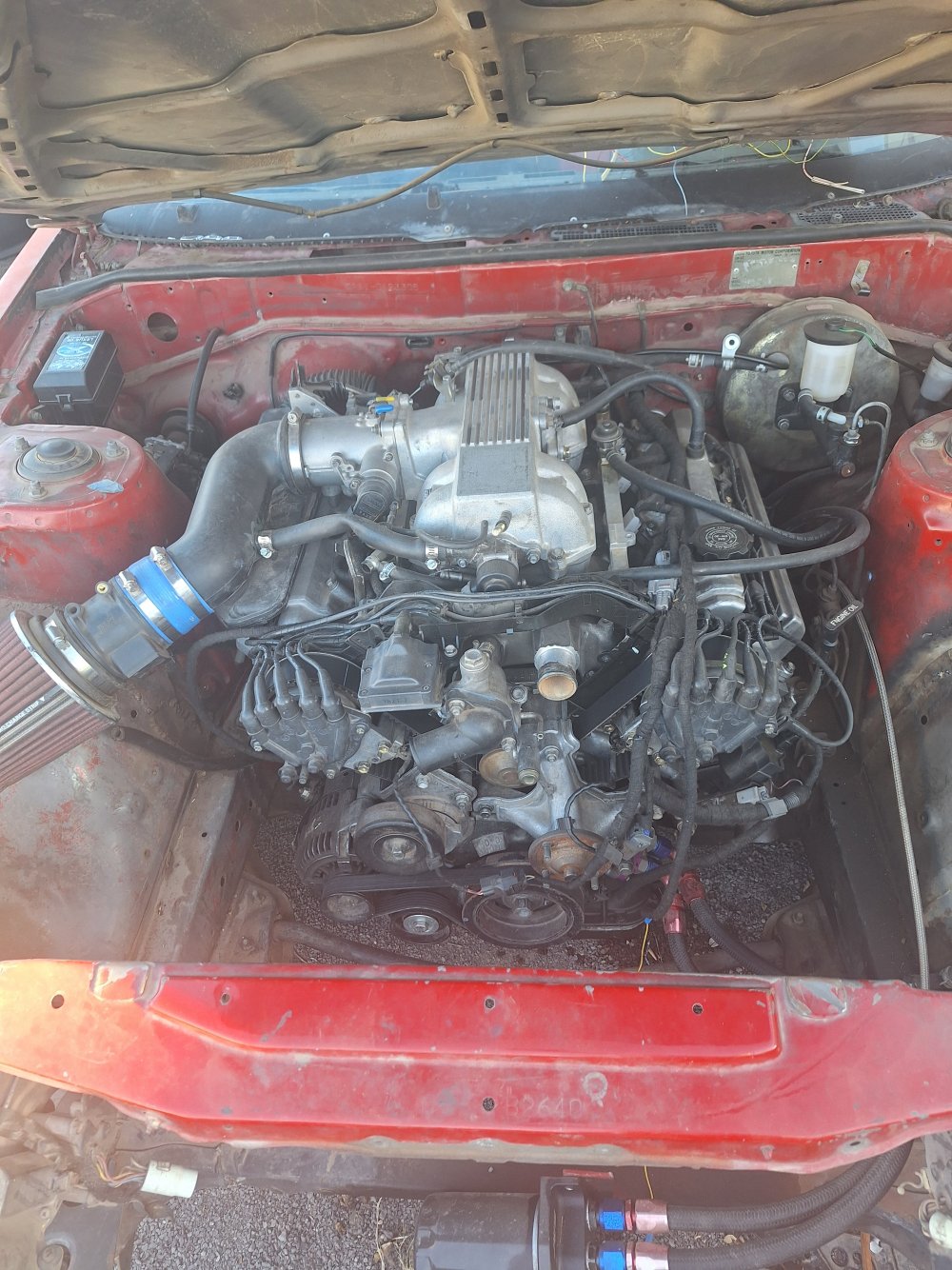
Hey all, ive been researching and struggling to get my UZ running in my gutted 84 celica for quite some time now. I had made a previous post when first buying the UZ asking about fuel rail differences and trying to find more information on what engine I have - all is well and I have this information now:
basic engine components (block, heads, fuel rails, crank cam) all from a 93 SC400 (nonVVTI), I am however, running 96 LS400 electronics and sensors(, also to my knowledge, nonVVTI electronics). I had bought a standalone harness for the UZ from LexusV8 down in florida when they had still offered their standalone services to nonVVTI UZ's. There is NO EGR and NO AUTO TRANS. The only engine codes im getting from an OBD2 reader are for missing transmission solenoids, alas - crank no start and i suppose i have some questions for the gurus here.
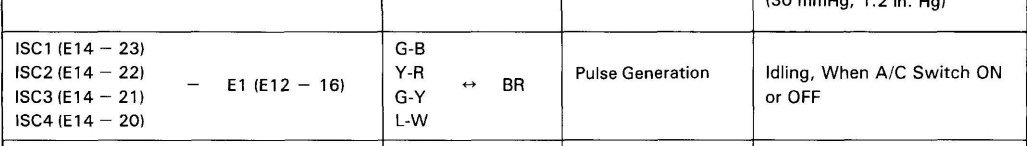
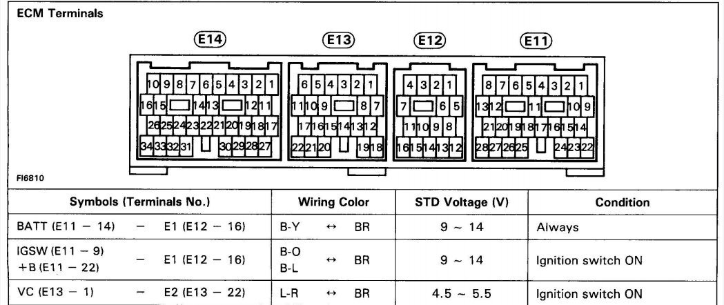
Im using a second gen maf, the crank trigger wheel is the correct tooth number, crank and cam sensors tested correctly when doing a resistance test, TPS is set and within spec, IACV is within specification and correctly steps through positions (I have both kinds of IACV but am currently running 'later' of the two P/Ns, as im running the ecu that expects this control valve).
I am getting fuel pressure (i do NOT have a secondary pressure regulator, although my engine is utilizing UCF10 rails and i think this gen has a FPR built in? havent VERIFIED a hard number on FP, though i doubt this may be it).
I am getting spark on all 8 (tested by pulling plug wires and inserting plug into wire while cranking), have plugged all vacuum ports I am not using, and im at a loss of where to check next.
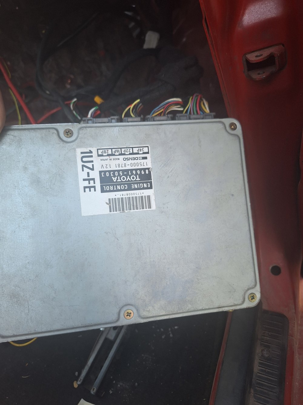
ECU toyo pn 89661-50303
I did just replace the capacitors within the ecu but fear i may have fried part of the board on one of the capacitor mounts, although after performing open brain surgery on it, the engine acts the exact same as it had prior to changing capacitors.
Would anyone happen to know if the ecu I have is supposed to be equipped with a matching immobilizer unit? -
Im asking this because theres nowhere else for me to look as to why this UZ isnt running. Im getting compression, Ive given it a full head tune-up (valve stem seals, lapped valves, headgasket changed) and reverified compression afterward.
So i have the basics > fuel, air, compression, spark
It seems to be backfiring through the intake occasionally, sputtering when cranking, sometimes cranking for a while without sparking, other times catching small attempts at an idle with the throttle all the way open. Ill include pictures and video if the site allows, just looking for any sort of direction from this post. TIA
- J Melo.
basic engine components (block, heads, fuel rails, crank cam) all from a 93 SC400 (nonVVTI), I am however, running 96 LS400 electronics and sensors(, also to my knowledge, nonVVTI electronics). I had bought a standalone harness for the UZ from LexusV8 down in florida when they had still offered their standalone services to nonVVTI UZ's. There is NO EGR and NO AUTO TRANS. The only engine codes im getting from an OBD2 reader are for missing transmission solenoids, alas - crank no start and i suppose i have some questions for the gurus here.
Im using a second gen maf, the crank trigger wheel is the correct tooth number, crank and cam sensors tested correctly when doing a resistance test, TPS is set and within spec, IACV is within specification and correctly steps through positions (I have both kinds of IACV but am currently running 'later' of the two P/Ns, as im running the ecu that expects this control valve).
I am getting fuel pressure (i do NOT have a secondary pressure regulator, although my engine is utilizing UCF10 rails and i think this gen has a FPR built in? havent VERIFIED a hard number on FP, though i doubt this may be it).
I am getting spark on all 8 (tested by pulling plug wires and inserting plug into wire while cranking), have plugged all vacuum ports I am not using, and im at a loss of where to check next.
ECU toyo pn 89661-50303
I did just replace the capacitors within the ecu but fear i may have fried part of the board on one of the capacitor mounts, although after performing open brain surgery on it, the engine acts the exact same as it had prior to changing capacitors.
Would anyone happen to know if the ecu I have is supposed to be equipped with a matching immobilizer unit? -
Im asking this because theres nowhere else for me to look as to why this UZ isnt running. Im getting compression, Ive given it a full head tune-up (valve stem seals, lapped valves, headgasket changed) and reverified compression afterward.
So i have the basics > fuel, air, compression, spark
It seems to be backfiring through the intake occasionally, sputtering when cranking, sometimes cranking for a while without sparking, other times catching small attempts at an idle with the throttle all the way open. Ill include pictures and video if the site allows, just looking for any sort of direction from this post. TIA
- J Melo.