You are using an out of date browser. It may not display this or other websites correctly.
You should upgrade or use an alternative browser.
You should upgrade or use an alternative browser.
can m112 snout be shorten if required?
- Thread starter zen
- Start date
The 1UZFE EGR Delete Kit is available for sale here.


Yes I did, that is why I asked to see inside. I want to see the mounting inside.
On my setup I am going to throw my manifold with supercharger on m flowbench and use baffles to direct part of the flow to the rear.
re how it bolts on..yep your spot on..oh..i see what you mean superrunner...the sides are made of angle,welded to the lower plate,nuts are welded on to the underside of angle( would have tapped the angle,but decided it was not thick enough..) ,the angle has been drilled through..the bolts will have locktight applied when sealing down and copperwashers under the heads..wont leak past them!!
and yes uneven air dis...i have thought about it..but not yet come up with a good solution..but it will involve a baffle to get more air towards rear ports.(which will have to be bolt on,so as i can get to the lower manifold to new upper bolts..).your thoughts??....(my sc outlet is towards front of manifold.)..i wont be using flow bench..you get an idea of the workshop at work..we run plant machinery,sweeper lorries to 22ton diggers..we fix the lot..i am the sparkie (which i am good at...save the boss thousands,just fixing that canbus node in the pic saved him £700,welder (mig),hydrolics and phematics man..workshop main tools are gas cutter..f off hammers,disc cutters..so i will be using my brain to work out what will work..no second chance, need to get it correct first go..
next here is a pic of intake (mk1)it has changeg since this photo,and been fully welded up..now the tb is lower..first 45 goes to 2 more 45's in a s type shape, lowering the tb by 1.5 inches.the straight bit has gone...the intake is held on by 4 bolts that go all the way though it..the bolt holes have a tube welded internally to keep the holes gas tight.ie no air can get in or out via holes wether bolted up or not.

next pic is of sc outlet.


currently it has 2 8mm threads and 4 6mm threads..not good enough to secure sc to upper plate..i intend to enlarge 6mmm threads to 8mm..will this be enough to secure sc down safely? i recon so...if not i can prehaps utilise front upper lugs and rear upper lug and clamp sc down.(not the prefered option!!!!)(see below for lugs)


Lextreme II
Just call me "Lex"
- Messages
- 12,033
- Location
- City of Halos
Bullet makes a special snout for the M112. Did u get some of my pictures?
- Messages
- 5,631
- Location
- Sydney, Australia
Shortening your blower snout may be harder than you think.
Work out the length you need then try and find out what car uses it.
Then find the Forum for those who frequent the appropriate Forum and you may find what you need at nominal cost.
If lots of members are discarding (or destroying) superchargers snouts may be cheap.
You'd be surprised how much Google & eBay can save you.
")
Lextreme II
Just call me "Lex"
- Messages
- 12,033
- Location
- City of Halos
I honestly think you will spend more money, time and headaches and multiple OOOOPS......It will be cheaper if you get the one that has been made.


SuperRunner
New Member
- Messages
- 657
- Location
- orem, ut
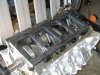
I would like to see inside your manifold to see how you are bolting down the top plate.
Plus how you going to get to those bolts inside the intake for the charger?
Plus how you going to get to those bolts inside the intake for the charger?
- Messages
- 5,631
- Location
- Sydney, Australia
Super Runner,
Did you notice the top plate of the new manifold bolts on.
I'd remove the bolts, remove the top plate and bolt the charger on then bolt the top plate back on, but that's just the way I'd do it.
Zen,
Have you thought about the uneven distribution of air between front/rear cylinders? This has been a problem with the twin screw superchargers.
My front cylinders ran lean and blew #1 cylinder.
Attachments
SuperRunner
New Member
- Messages
- 657
- Location
- orem, ut
Super Runner,
Did you notice the top plate of the new manifold bolts on.
I'd remove the bolts, remove the top plate and bolt the charger on then bolt the top plate back on, but that's just the way I'd do it.
Yes I did, that is why I asked to see inside. I want to see the mounting inside.
Zen,
Have you thought about the uneven distribution of air between front/rear cylinders? This has been a problem with the twin screw superchargers.
My front cylinders ran lean and blew #1 cylinder.
On my setup I am going to throw my manifold with supercharger on m flowbench and use baffles to direct part of the flow to the rear.
Super Runner,
Did you notice the top plate of the new manifold bolts on.
I'd remove the bolts, remove the top plate and bolt the charger on then bolt the top plate back on, but that's just the way I'd do it.
Zen,
Have you thought about the uneven distribution of air between front/rear cylinders? This has been a problem with the twin screw superchargers.
My front cylinders ran lean and blew #1 cylinder.
re how it bolts on..yep your spot on..oh..i see what you mean superrunner...the sides are made of angle,welded to the lower plate,nuts are welded on to the underside of angle( would have tapped the angle,but decided it was not thick enough..) ,the angle has been drilled through..the bolts will have locktight applied when sealing down and copperwashers under the heads..wont leak past them!!
and yes uneven air dis...i have thought about it..but not yet come up with a good solution..but it will involve a baffle to get more air towards rear ports.(which will have to be bolt on,so as i can get to the lower manifold to new upper bolts..).your thoughts??....(my sc outlet is towards front of manifold.)..i wont be using flow bench..you get an idea of the workshop at work..we run plant machinery,sweeper lorries to 22ton diggers..we fix the lot..i am the sparkie (which i am good at...save the boss thousands,just fixing that canbus node in the pic saved him £700,welder (mig),hydrolics and phematics man..workshop main tools are gas cutter..f off hammers,disc cutters..so i will be using my brain to work out what will work..no second chance, need to get it correct first go..
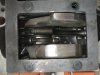
next here is a pic of intake (mk1)it has changeg since this photo,and been fully welded up..now the tb is lower..first 45 goes to 2 more 45's in a s type shape, lowering the tb by 1.5 inches.the straight bit has gone...the intake is held on by 4 bolts that go all the way though it..the bolt holes have a tube welded internally to keep the holes gas tight.ie no air can get in or out via holes wether bolted up or not.
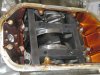
next pic is of sc outlet.
currently it has 2 8mm threads and 4 6mm threads..not good enough to secure sc to upper plate..i intend to enlarge 6mmm threads to 8mm..will this be enough to secure sc down safely? i recon so...if not i can prehaps utilise front upper lugs and rear upper lug and clamp sc down.(not the prefered option!!!!)(see below for lugs)
at this stage now..
http://www.lextreme.com/forums/showthread.php?p=104969#post104969
still need info on will 6 m8 bolts holding sc down be enough?
and need info on how bypass valve limits max boost..if indeed it does..(i know how it works at idle etc..) just not sure if it limits max boost or if it can be made too..i recon it can, by using an actuator that works on boost and vac..i expect thats what they do...can you confirm please..?
- Messages
- 5,631
- Location
- Sydney, Australia
6 x 8mm bolts should hold it down.
My twin screw has 5 8mm bolts holding it down so 6 should be better.
The by-pass valve only operates at low vacuum so at idle and cruise.
It doesn't limit boost in any way. xcept if it leaks!
A twin diaphram valve may be able to do it but I have no idea as that's one thing I don't want to restrict.
My twin screw has 5 8mm bolts holding it down so 6 should be better.
The by-pass valve only operates at low vacuum so at idle and cruise.
It doesn't limit boost in any way. xcept if it leaks!
A twin diaphram valve may be able to do it but I have no idea as that's one thing I don't want to restrict.
Similar threads
- Replies
- 18
- Views
- 5K
- Replies
- 1
- Views
- 1K
- Replies
- 15
- Views
- 7K
- Replies
- 29
- Views
- 14K
- Replies
- 3
- Views
- 5K
- Replies
- 10
- Views
- 5K
- Replies
- 6
- Views
- 3K