Reincarnation: 1uzfe reanimates 4runner with impending flatline

The 1UZFE EGR Delete Kit is available for sale here.
ENGINE INSTALLATION PROPPER: Cooling Issues​

Cooling, or lack there of, has been an issue for many guys doing this conversion due to the smallish engine bay creating restricted airflow. I did a fair bit of reading to see what other guys had done and discussed this at length with the mechanics before I handed the vehicle over for the conversion.

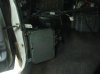
Before I took the vehicle to the mechanics I moved the winch box under the bonnet near the brake master cylinder. This normally sits smack in the middle of the bull bar in front of the radiator and robs it of air. Moving it inside the engine bay gives it a bit of protection as well as creates more airflow through the radiator.

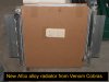
I ordered from Scott at VENOM COBRAS in Qld an alloy radiator for about $700 that fits the 4runner. It is apparently a Nascar quality AFCO Racing radiator. Scott was able to get the exit and entry holes welded on opposite sides as the V6 and V8 have their hoses on opposite sides. This radiator also had the support brackets welded half way along the tank.

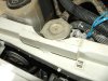
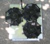
The new alloy radiator was recessed forward to create more room for thermo fans between the engine and radiator.

In short, the front radiator panel support was cut and enlarged to recess the radiator forward, taking advantage of the radiator support brackets welded half way along the radiator tanks. This created more precious room between the fan and pullies on the front of the engine – remember we are fighting for mere millimetres here.
 

Attachments

  • 1uzfe - aluminium radiator 00.jpg
    1uzfe - aluminium radiator 00.jpg
    111.5 KB · Views: 48
  • Alloy Radiator setup 01 copy.jpg
    Alloy Radiator setup 01 copy.jpg
    51.6 KB · Views: 23
Last edited:
1uzfe Reincarnated 4runner: Project Frankenkryst

ENGINE INSTALLATION PROPPER: Strengthening bonnet support bar​

Part of the top of the bonnet support bar had to be cut and (then reinforced at the insistence of the engineer) to allow for the radiator cap in this new setup.

Bars were also welded across the front between the radiator support panels to strengthen the area around the radiator.
 

Attachments

  • Radiator cap 01.jpg
    Radiator cap 01.jpg
    125.6 KB · Views: 40
Last edited:
ENGINE INSTALLATION PROPPER: Installation of thermo fan​

A 14 inch thermo fan was installed and thermo switch but I later replaced this with a shroud and three 9 inch thermo fans, and then I managed to install a 16 inch thermo fan with a new PWR radiator. More on this later in the post engine installation build up phase.
 
Last edited:
ENGINE INSTALLATION PROPER: Transmission and Transfer Shifter Levers​

The original shifter lever assembly was replaced by that from a Toyota Surf. This was to accommodate the auto shifter for the main box and the manual stick for the transfer case. This surf assembly was actually mounted up to several of the pre-existing bolt holes with only a few more bolt holes needing to be drilled.

Some cutting of the transmission tunnel toward the rear was necessary. I don’t believe the linkage between the shift arm and the gearbox arm needed any modifications.

I have already described how I adapted the transfer case lever to the new setup so I won’t go into it again (see previous posts).

A PWR transmission cooler was installed above the LPG gas tank up the back of the vehicle to keep the tranny fluid cool.
 

Attachments

  • Shifter levers 01.jpg
    Shifter levers 01.jpg
    130.3 KB · Views: 19
Last edited:
ENGINE INSTALLATION PROPER: Power Steering​

The power steering pump and reservoir on the V8 connected with little trouble to the 4runner steering box as they were on the same side. New power steering hoses were used. There is a PS cooling loop at the bottom of the radiator on the V6 4runner, this was retained.


ENGINE INSTALLATION PROPER: Driveline Components​

Drive shafts mods – rear driveshaft lengthened and front driveshaft shortened and rebalanced as the transfer case moved rearward and up a couple of inches.


ENGINE INSTALLATION PROPER: Grounding the new motor.​
Several large wires were installed to earth the motor to the chassis


ENGINE INSTALLATION PROPER: Fuel System​

The original V6 fuel pump was used and this works fine.

New fuel lines were adapted, the inlet is now on the rear of the passenger side fuel rail and the regulator / return is on the rear of the driver’s side fuel rail.

After I took delivery of the converted 4runner I modified a bracket to house a new charcoal canister on the passenger side fire wall.

After the LPG system was reinstalled, the LPG mechanic had the fuel pump run while the injectors were off so that fuel would continue to circulate through the fuel lines and prevent them from being gummed up by the accumulation of deposits.
 
Last edited:
ENGINE INSTALLATION PROPER: Computer and Engine Management Wiring

The black art or wiring remains a mystery to me so I got Jim (Sideshow of this website) to come and do it all once the mechanics had completed the engine mounts, fuel lines, power steering etc. It was completed in a single day and a black box was added so that the V6 tacco could read the signal from the V8 engine (A couple of months later I changed this by removing the blackbox and installing a 4 cylinder petrol hilux tacho in the dash. The black box didn’t need replacing but I found the hilux at the wreckers and thought what the hey). Other than a misbehaving OD light (that was later fixed by Jim in 2 minutes with a changeover relay) I have had absolutely NO issues with the wiring. The car has been driving properly ever since.

The computer was left behind a kick panel in the passenger foot well where the old one used to go so I could mount it later. This ended up being a pain in the azz as it is huge (bigger than a DVD case and twice as thick) and there are not many other places to put it. I don’t know why Toyota mount these here on a 4wd, as they are very prone to water ingress on river crossings. If the wiring loom was a bit longer it would be easier, I could have perhaps installed it safely up over the glove box.
 

Attachments

  • Computer 03.jpg
    Computer 03.jpg
    195.3 KB · Views: 25
Last edited:
ENGINE INSTALLATION PROPER: Air Conditioning​

I had the air con reinstalled during the installation. This was a big job as the compressors on the old and new engines were on the opposite sides. All the piping had to be reinstalled. The guys at Hi tech 4x4 handed it over to an air-con guy in Penrith for this stage of the build. Unfortunately not long after I took delivery of the vehicle there was a gas leak somewhere in the system and it emptied itself. It has to be fixed and re-gassed at some stage.

The air con guy had also mixed the polarity of the wires on the pusher fan on the front of the condenser and it was actually pulling hot air back through the radiator when it came on. When I first tried the air-con the car took about 30 seconds to start climbing into the red on the temp gauge. I fixed this by correcting the polarity on the fan.
 
ENGINE INSTALLATION PROPER: Adaptation Of Oil And Transmission Dipstick Tubes​

Both the engine oil and transmission oil dipstick tubes had to be modified slightly by bending due to the installation of the different engine hugging exhaust manifolds.

The engine oil dipstick originally went through a loop on one of the pipes but once the tighter crown manifolds were installed it had to pass around the outside.
 

Attachments

  • Dipstick tube position before 01.jpg
    Dipstick tube position before 01.jpg
    152.7 KB · Views: 17
Last edited:
ENGINE INSTALLATION PROPER: Miscellaneous Fluids And Filters​

Finally new air, fuel and oil filters were installed. As the oil filter comes perilously close to the chassis rails I bought a tiny one from Sideshow who has a good supply of them. I later replaced this with a remote oil filter kit, which makes the oil filter much easier to remove and replace (I don't even have to get on the ground, just open the bonnet, reach in and twist) and I can also use a much larger filter.

The hardest part of installing this was running the hoses so that they are not kinked or crushed on formwork about the engine bay. Using a remote filter also allows you the option of running an oil cooler too, though I have not installed one. I'll post pix of this one soon.

Coolant, oil, power steering fluid, transmission fluid etc were added.
 

Attachments

  • oil filter 03.jpg
    oil filter 03.jpg
    125.8 KB · Views: 40
  • Remote Oil Filter Location 01.jpg
    Remote Oil Filter Location 01.jpg
    144.3 KB · Views: 22
Last edited:
Part 4: POST ENGINE INSTALLATION WORK

After about four months the guys at Hi Tech had completed their part in this swap. But the fun did not end once I got the vehicle back. There was a mountain of little things, tidying up, tweaks and changes that I seemed to spend ages sorting out and completing. I will not go into them all here but I will list some of the major ones.
 
Last edited:
POST ENGINE INSTALLATION: Battery​

The 700CCA Century battery was quite large and was only millimetres from the Power steering reservoir. I didn’t want to risk the battery being punctured or holed while bouncing around off road, spitting acid everywhere, so I replaced it with a slightly smaller 650CCA battery. There is plenty of room there now.
 
POST ENGINE INSTALLATION: Snorkel reinstallation, Air Intake and air Box​

I bought 4 sections of air hose and two air boxes for a VN commodore from the wreckers. The hoses are 80mm in diameter and fit over the AFM and throttle nicely. With a bit of chopping and fibre glassing of the VN air boxes I managed to rig up an air box that allowed for the reinstallation of the LPG mixer, the AFM and the snorkel. Due to space I was not able to rig all of these up with the previous air box. I used wire mesh through the fibreglass to add strength. Over a year of driving and off-roading and still no cracks. This was later replaced with a fabricated aluminium one. more on this later.
 

Attachments

  • Air Box construction 01.jpg
    Air Box construction 01.jpg
    94.4 KB · Views: 18
Last edited:
POST ENGINE INSTALLATION: Computer Mounting​

The computer sat loose behind the kick panel for about a week till I figured out where and how to bolt it to the body. The computer for these engines is so damn big it is hard to find a spot for them. It ended up where the old one was mounted on the passenger side foot well wall. I am not sure why Toyota mounted the computers of a 4wd here in the first place as it is quite a vulnerable spot for water ingress during mud hole/river crossing. So until I could come up with a better alternative I went over all the bolts and seams on the box with some silicone to try and prevent water ingress, if water should ever get in the cabin.
 

Attachments

  • Computer location.jpg
    Computer location.jpg
    177.7 KB · Views: 19
Last edited:
POST ENGINE INSTALLATION: Aluminium fan shroud.​

Ask most of the guys who have done this swap into a 4runner/hilux and they will all tell you that a decent amount of time and effort had to be spent sorting the cooling due to space and overheating problems under the bonnet. And each person’s solution is usually completely different.

As previously described I used an aluminium radiator supplied by venom cobra’s in Queensland, and had it recessed forward to create a bit more room for a fan between the radiator and engine. The Hi-Tech mechanics originally installed a 14 inch thermo fan with no shroud to get it running. This 14 inch fan worked pretty good to begin with but it was a 42 degree day crawling up a few tracks in Barrington tops with the cooling system struggling that made me decide to try and sort it all out. A 16 inch fan would have been ideal but would not fit between the radiator and engine pulleys; it was about a centimetre too fat.

Even though a 16 inch Davies Craig would not fit, multiple smaller ones would. So after doing a bit of research on flow rates and getting under the bonnet with a tape measure, I knocked out an aluminium fan shroud and fitted it up. I used 3 x 9 inch thermo fans, which allowed a radiator shroud that was about 1.5cm to 2cm deep. Comparing the flow rates, the figures weren’t too bad, almost the same as a 16 inch fan.

16 VOLUME FLOW = 2120 CFM (1000 Litre/s) (would have been ideal if it had fit!)
14 INCH VOLUME FLOW = 1270 CFM (600 Litre/s) (the size originally installed)
9 INCH VOLUME FLOW = 635 CFM (300 Litre/s) (635 x 3 = 1905 CFM (900 Litre/s)) (the present setup)

At the top of the shroud I doubled it over and bent a lip that would allow it to hang off the metal edge at the top of the radiator. The theory being that even if the retaining bolts holding the shroud fell out then the whole structure would “hang” there and not fall out on the ground. I mounted the fans in positions where their hubs (the fattest part of the fan) sat between the engine pulleys in case the engine moved. At the closest point the fans and pulleys are about 2cm/1 inch apart.

I put rubber edges down the sides so the aluminium edges would not cut into the thin metal channels on the radiator if the shroud ever got bent. Once the fans and the shroud were physically installed I rigged up the wiring to three relays that are switched on and off from a thermo switch. They switch on at about 85 degrees.
 

Attachments

  • fans 10.jpg
    fans 10.jpg
    171.3 KB · Views: 17
  • Fans 02.jpg
    Fans 02.jpg
    136 KB · Views: 36
  • Fans 11.jpg
    Fans 11.jpg
    126 KB · Views: 36
Last edited:
85degrees seems a little early to turn on the fans.

Mine come on at 95 and I'm thinking about moving up to 100.

The thermostat is only just opening at 85.
 
G'day Rod,

What is the best temp to run these motors at? I always thought between 80 and 90 was the go? Should it be hotter?
 
Thanks peewee:fing02:

I might up it to 90 and see how she likes it. Do you change the thermo switch setting between winter and summer of leave it constant? I know this subject has been done to death in some quarters but some people say they don't run thermostats with these motors to increase cooling, is that a good idea?
 
I never a good idea to run without a thermostat.
It increases wear on the motor and uses extra fuel.

Set it up so that it runs normal in summer and it will be fine in winter, the thermostat will take care of that.


Top