Reincarnation: 1uzfe reanimates 4runner with impending flatline

The 1UZFE EGR Delete Kit is available for sale here.
Hey, thanks Matt!

The radiator and cooling took a while to get right and being as hot as it is here in Oz during summer it is one part of the build I didn't want to skimp on. Engine temperatures are well under control ATM. I am thinking of turning the scoop around when it starts hotting up here again to let the engine bay breathe a bit better.
 
Love the buildup, looks fantastic!
Quick question, reversing the intake plenum,
was it as simple as just unbolting, rotating and bolting back on?
Or more to it than that?
 
G’day timmay5.7

Yes and no…. The plenum just spins straight around and fits back on but there is a whole bunch of stuff you have to do to make it all work properly. See posts 40 to 58 for details. Basically the following had to happen:

Plenum and intake manifold
• The four centre bolt pins on the intake manifold need to change sides
• Idle speed controller (ISC) goes from front to back so may foul against the wiring harness at the back of the engine. The wiring harness may need to be moved or adjusted
• The ISC may also foul on the metal heater hose output/input from the motor. The heater hose needs to be bent slightly out of the way.
• The small coolant hose that runs under the throttle and ISC will most likely need to be deleted and the small pipes cut off the ISC and throttle due to fouling.

Control Cables
• throttle and gearbox cables need to be rerouted and positioned correctly
• You may need to get new cables to fit.

Plumbing
• Idle speed controller input moves from front to back of the plenum. Hoses and wires adjusted accordingly
• Some other smaller tubes on there need to be re-routed but can’t remember where they go at the moment.
• PCV valve inlet hose moved.

Wiring
• the throttle position sensor needs to go to the opposite side
• Idle Speed Controller wiring goes from front to rear of plenum because ISC moves from front to back of the plenum
• Airflow metre plug needs to swap sides.
• There may be some other wires but I can’t remember them all at the moment.

See posts 40 to 58. Hope this all helps.
 
POST ENGINE INSTALLATION: Replacement of 4runner V6 tacho with Hilux petrol 4 cylinder tacho

Sorry guys, been a bit busy of late and have not posted here for a while. I completed most of this stuff last year but have only recently gotten around to writing it up and posting it.

As the title says I replaced the 4runner V6 tacho with Hilux petrol 4 cylinder tacho. There was nothing wrong with the little black box supplied to me by Sideshow, but I wanted to make the electricals about the ECU and the passengers feet a bit simpler and I was able to pull a 4 cylinder tacho out of a hilux.

Replacing it was as simple as pulling the dash apart and opening up the instrument cluster then undoing a few screws. Very simple.
 

Attachments

  • Hilux 4 cylender tacho 01.jpg
    Hilux 4 cylender tacho 01.jpg
    157 KB · Views: 16
Last edited:
POST ENGINE INSTALLATION: Aluminium radiator hose bend​

I put this 38mm alloy bend in as the old rubber bend that delivered coolant from the bottom of the radiator back into the engine came close to the top fan housing on the new radiator fan shroud setup. I didn’t want them inadvertently rubbing and putting a hole through the rubber hose. This pipe ensures that in the unlikely event that there is rubbing between the two then there will not be any holes and coolant jetting out everywhere.
 

Attachments

  • Alloy radiator hose bend 01.jpg
    Alloy radiator hose bend 01.jpg
    154.1 KB · Views: 16
Last edited:
POST ENGINE INSTALLATION: Replaced rear window motor​

This isn't really related to the engine conversion But I thought it worth mentioning as it may help some of you guys.

The rear window motor was slowly clagging out so I went to the wreckers to get a new one. I thought these would be pretty scarce and expensive but the wrecker told me that they were the same motor used on the side windows (left side I think (passenger AUS, UK, Driver US, Europe)). There were 2 part numbers on this motor: 85710-35050 and 062100-5200. Replacing was fairly straight forward and was a matter of putting the tailgate down and getting to everything under the carpet covered panel. You have to undo the armature and pull the window up to get to the motor. Watch those window arms as you undo everything as they are spring loaded and will take the tip of your finger off if you are not careful.
 

Attachments

  • Rear Door Motor 02.jpg
    Rear Door Motor 02.jpg
    121.4 KB · Views: 10
Last edited:
MISCELLANEOUS MODIFICATIONS: NARVA INTERIOR FLURO LIGHT​

Again, not engine conversion related but this may be of interest to some.

Since the factory interior light is complete shizer and you are better off using a match, I got one of these. A 12 volt, 13 watt fluorescent interior dome light. It took about half an hour to install, and is very bright. Narva part number 87320 I think.
 

Attachments

  • Narva Dome Light 01.jpg
    Narva Dome Light 01.jpg
    77.8 KB · Views: 11
Last edited:
POST ENGINE INSTALLATION: Powder Coating Part 2​

I finally got around to re-powdercoating the plenum chamber and the valve covers. Because I turned the plenum around the conventional 1UZ plastic engine covers no longer fit around the valve covers and plenum. So to make it all look a bit more presentable and to stop bolts and sockets falling down in the valley of the V, I also got some cardboard and cut out a template for a cover to go where the plastic engine covers normally go. I got some metal hex pattern mesh, cut out a cover from it using the cardboard template, bent it up so that would fit and powder coated it black. Finally I put some rubber edging around it so that it would not scratch into my new expensive shiny orange powder coat and installed it on the engine. Looking at it now I think I actually prefer the metal mesh to the plastic covers, it looks a bit cleaner and not as fussy.

I had a spare Toyota badge lying around so I stuck it on the side to make it that bit more presentable. Overall I think it turned out pretty good. With the Orange powdercoat, the metal mesh and the badge all up there was a 42 Brake Horsepower gain at the wheels.
 

Attachments

  • Engine mesh cover 01.jpg
    Engine mesh cover 01.jpg
    118.3 KB · Views: 19
  • Engine Powdercoat finished 06.jpg
    Engine Powdercoat finished 06.jpg
    125.9 KB · Views: 22
  • Engine Powdercoat finished 07.jpg
    Engine Powdercoat finished 07.jpg
    113.4 KB · Views: 18
Last edited:
POST ENGINE INSTALLATION: Autometer Coolant temp gauge​

I installed a Autometre coolant temp gauge (Celsius not Fahrenheit). The gauge went on the “A” pillar of the cabin. I cut the top radiator hose (the one from engine to radiator) and installed a 38mm adapter to fit the temp sensor sender. Almost forgot to earth the body of the adapter with a separate wire leading to a decent ground point on the body of the vehicle. If I had not have done this the gauge would not have shown anything at all.
 

Attachments

  • Coolant Temp Gauge 01.jpg
    Coolant Temp Gauge 01.jpg
    176.5 KB · Views: 18
Last edited:
POST ENGINE INSTALLATION: LPG Reinstallation​

The LPG re-install happened over a year ago but here it is now. Before reinstalling the LPG, I rerouted some of the heater hoses so that they ran back through the gas converter.

I took the vehicle it back to the people who originally installed the LPG. After a week of doing nothing to the vehicle they spent 2 hours on a Friday afternoon ripping some wires out before telling me it was all all too hard for them and they could not do it. They eventually gave me the car back a week later with all the LPG wiring ripped out and exposed. The charcoal canister was also just left hanging loose behind the wiring loom waiting to fall out on the first dirt road I went up. They should have know better too, as they were 4wd Mechanics.

Pretty much all that was needed was to have a relay interrupt the earth wire from the injectors. I took the vehicle to Sideshow and within half an hour he had isolated the injector’s earth wire and made a loop the LPG mechanic could tap into. I then took it to another LPG mechanic and it was all reinstalled and running within two days. He tidied the wiring and made the setup much simpler. There is now a single relay, a fuse and a small computer. The original mixer and converter were retained. He also installed a new diaphragm in the mixer.

The fuel pump runs while using LPG (when the injectors are off) so that petrol continues to circulate through the fuel lines and rails and prevent them from being gummed up by the accumulation of deposits in the petrol.

Performance wise I can barely tell the difference between petrol and LPG.

(Sorry about the mud splatters in the pix)
 

Attachments

  • LPG heater hose config 01.jpg
    LPG heater hose config 01.jpg
    189.4 KB · Views: 11
  • LPG relay and control box.jpg
    LPG relay and control box.jpg
    119.5 KB · Views: 9
Last edited:
CABIN MODIFICATIONS: Toyota Surf Inclinometre​

I saw a Toyota Surf Inclinometre on Ebay so grabbed it, put a red LED in it and installed it on the dash. It was a huge PITA as you pretty much have to get the whole dash apart to bolt it on and wire it up. As usual with the dash, I left it till a bunch of behind the dash jobs came up then did them all at once.
 

Attachments

  • Inclinometre 01.jpg
    Inclinometre 01.jpg
    170.5 KB · Views: 15
Last edited:
Awesome you got the LPG going! I'm totally interested in something like that. I want to do HHO maybe after my truck is complete and I need something else to do. That inclinometer is a great idea as well. I would have to make it removeable for when I go offroad. It would drive me nuts. The rig is looking pretty nice.
 
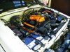
Yeah no worries Peewee. I was surprised at the way it turned out and I think it actually looks a bit neater than the plastic covers as it is all one single piece that keeps the dimensions/angles of the plastic cover over the spark plug leads at the front of the engine. I used metal with hex holes but you can get other patterns too, like squares circles etc. I think all the perforated holes help the hot air circulate from under the plenum a bit better than the old plastic covers too. Plus, no more missing sockets down that gaping hole into the valley of the V.

I think I still have the cardboard template around somewhere. If i find it I could PM you the dimensions, save you an hour or two under the bonnet chopping up cardboard. I guess you could turn it upside down if your plenum and throttle are in the original position, and you may have to do some minor chopping or changes based on your own setup but the basic layout would be the same I guess.
 
We used the factory temp gauge from the previous engine mounted as a second temp sensor on the 1uz engine, that way you can re-use the in dash gauge
G'day Anodyne,

Yeah, I reused the in-dash one as well, using the old v6 sender in the coolant bridge at the front of the engine. It works just fine but I wanted something a bit more accurate that takes the guess work out of reading temps. With the thermostat installed the motor seems to consistently sit on 90C (194F). I have read that between 90C (194F) and 104C (220F) is pretty much normal operating temps for these motors, Is this correct? (Peewee, Lex or Zuffen may have a good idea of this one).

You may have already seen it but this site on a mod for the factory temp gauges for 4runners/Surfs/Toyota's is interesting:

http://www.toyotasurf.asn.au/forum/viewtopic.php?t=14717&
 
BODY MODIFICATIONS: Front bash plate

The standard factory bash plate on these vehicles is made of mild steel about 0.8mm thick and does not stand up to much punishment. It is adequate and serves a purpose protecting the frontal area, but it gets beat up and bent pretty quick once you take it off road. I got tired of looking at it and wondering when it was going to get ripped off by a tree branch or rock.

So one afternoon I made a template from some cardboard and took it to an aluminium fabrication mob. They bent me up a new bash plate from some 6mm thick aluminium. I then got it powder coated black to match the bull-bar. I have not compared the weights but they feel like they are similar in weight.

It looks much better than the old factory bash plate. Unfortunately I only have pics of the new one, I will try to get some of the old one later so you can see just how much of an improvement it is.
 

Attachments

  • Bash Plate.jpg
    Bash Plate.jpg
    186 KB · Views: 39
G'day Bushwhacker,

How's it going? Yeah, I was wondering that myself.

There are even some pictures that are not mine that have appeared on here. Since the Lextreme site's big crash all my pictures have disappeared so I think it had something to do with that. I know the administrators and mods have all been busy trying to fix everything on the site and I am reluctant to bother them with PMs asking them what is going on. They got smashed with PMs and I didn't want to become a nuisance. Maybe I should PM them now the crash was a few weeks ago....

You can see the bash plate ones because I only posted that one the other day (ie after the big crash).


Top