Hi All,
I have been lurking on the forum for some time jealously watching you getting on with your conversions and collecting lots of good information in readiness for my own project.
The time has finally come and I have embarked on what I suspect will be a lengthy and challenging conversion.
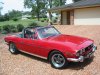
My aim is to shoehorn 1uz vvti goodness into a 1974 Triumph Stag. These vehicles have been the recipient of many different engines and some are easier to fit than others. I know some of you will think I’m mad because it would be easier to put something like an LS1 or hotted up Rover motor in the car but I like the idea of an overhead cam fuel injected V8 as I think it is in keeping with Triumph’s original objectives. The original engine is a 3 litre overhead cam V8 with alloy heads and twin Stromberg carburettors. Triumph had originally intended to use fuel injection but couldn’t get it to meet the US pollution requirements. They also developed four valve heads for the Dolomite Sprint motor which is effectively half a Stag motor. It is a shame Triumph did not have the resources to refine the Stag V8 with fuel injection, four valve heads and improved reliability for it would have become a cult classic. In a way I hope to create the car that could have been.
I will be using the standard 5 speed auto and ecu as I think I will have enough challenges without trying to convert to a manual and/or an aftermarket ecu. With 215kw and 400nm torque I think the performance will be sufficient for my needs. As the intention is to make the car an everyday driver I will be trying to keep the air con.
In doing this conversion I will be drawing on the excellent work Andrew (Sparrow010) has done in fitting a non vvti 1uz into his prize winning Stag. If I can achieve half the quality he has I will be happy.
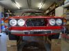
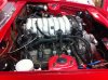
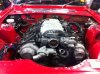
Enough chit chat – here’s what I’ve managed so far. The motor has been trial fitted to identify clearance issues and there are a few. I have attached some photos to show the issues.
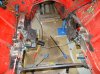
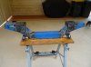
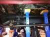
The 1uz is approximately 30mm taller than the Stag motor so to get it under the bonnet requires dropping the cross member, complete with steering rack, about 25 to 30mm. Doing this means there isn’t much meat left in the couplings so some trickery may be required here. Looks like I will have to drop the sway bar mounting too.
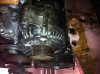
The cross member sits towards the front of the motor so a rear sump is called for and thanks to Zuffen I now have one of these hard to get items. Even so it will need some modification and I am hoping the mods Andrew made to his will give me the clearance I need. To fit the sump behind the cross member will necessitate keeping the motor as far back as possible. To achieve this I might have to redo the wiring around the back of the motor and get rid of the plastic cable tray.
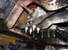
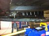
The inlet manifold on the vvti unit appears to be the same height as the non vvti one but is wider and extends further forward and back which means it fouls the bonnet catch.
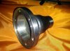
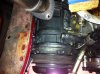
Output from the A650 transmission is via a 150mm dia donut for which there is no room under the Stag. I have removed the yoke and am hoping to use a spline drive to the prop shaft similar to the original Triumph approach.
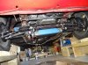
Keeping the a/c compressor means there isn’t a lot of room between the chassis rails but I think I can just squeeze it in if I grind a lug off the alternator.
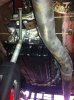
There won’t be much room for the exhaust headers either so I will need some that are tight against the heads but hoping to avoid log style headers.
Just to make things even more fun the right hand engine mount will have to be located directly over the steering gearbox.
That’s enough for tonight. Of course any advice and/or assistance will be greatly appreciated. Will I have the resources and stamina to complete this? We’ll just have to watch and wait.
Cheers,
Barry
I have been lurking on the forum for some time jealously watching you getting on with your conversions and collecting lots of good information in readiness for my own project.
The time has finally come and I have embarked on what I suspect will be a lengthy and challenging conversion.
My aim is to shoehorn 1uz vvti goodness into a 1974 Triumph Stag. These vehicles have been the recipient of many different engines and some are easier to fit than others. I know some of you will think I’m mad because it would be easier to put something like an LS1 or hotted up Rover motor in the car but I like the idea of an overhead cam fuel injected V8 as I think it is in keeping with Triumph’s original objectives. The original engine is a 3 litre overhead cam V8 with alloy heads and twin Stromberg carburettors. Triumph had originally intended to use fuel injection but couldn’t get it to meet the US pollution requirements. They also developed four valve heads for the Dolomite Sprint motor which is effectively half a Stag motor. It is a shame Triumph did not have the resources to refine the Stag V8 with fuel injection, four valve heads and improved reliability for it would have become a cult classic. In a way I hope to create the car that could have been.
I will be using the standard 5 speed auto and ecu as I think I will have enough challenges without trying to convert to a manual and/or an aftermarket ecu. With 215kw and 400nm torque I think the performance will be sufficient for my needs. As the intention is to make the car an everyday driver I will be trying to keep the air con.
In doing this conversion I will be drawing on the excellent work Andrew (Sparrow010) has done in fitting a non vvti 1uz into his prize winning Stag. If I can achieve half the quality he has I will be happy.
Enough chit chat – here’s what I’ve managed so far. The motor has been trial fitted to identify clearance issues and there are a few. I have attached some photos to show the issues.
The 1uz is approximately 30mm taller than the Stag motor so to get it under the bonnet requires dropping the cross member, complete with steering rack, about 25 to 30mm. Doing this means there isn’t much meat left in the couplings so some trickery may be required here. Looks like I will have to drop the sway bar mounting too.
The cross member sits towards the front of the motor so a rear sump is called for and thanks to Zuffen I now have one of these hard to get items. Even so it will need some modification and I am hoping the mods Andrew made to his will give me the clearance I need. To fit the sump behind the cross member will necessitate keeping the motor as far back as possible. To achieve this I might have to redo the wiring around the back of the motor and get rid of the plastic cable tray.
The inlet manifold on the vvti unit appears to be the same height as the non vvti one but is wider and extends further forward and back which means it fouls the bonnet catch.
Output from the A650 transmission is via a 150mm dia donut for which there is no room under the Stag. I have removed the yoke and am hoping to use a spline drive to the prop shaft similar to the original Triumph approach.
Keeping the a/c compressor means there isn’t a lot of room between the chassis rails but I think I can just squeeze it in if I grind a lug off the alternator.
There won’t be much room for the exhaust headers either so I will need some that are tight against the heads but hoping to avoid log style headers.
Just to make things even more fun the right hand engine mount will have to be located directly over the steering gearbox.
That’s enough for tonight. Of course any advice and/or assistance will be greatly appreciated. Will I have the resources and stamina to complete this? We’ll just have to watch and wait.
Cheers,
Barry
")