supercharger intercooler manifold problem.

The 1UZFE EGR Delete Kit is available for sale here.

striker

New Member
Messages
602
Location
holland
Ok here's a problem

I've finnaly got around a big problem regarding my laminova intercoolers, solidworks draw will be next week and milling in the not to distant future.

anyway here goes,

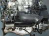
stock lower inlet manifold will be milled down on to the flat alloy pieces where the injectors spacer sit upon. on to of whats left the IC stack will take place that will be only 45mm high. + 1 cm to get clearance inbetween the stack and milled down intakes.

the combined hight of this will then be 30mm short of 60cm total engine hight (yes thats true) BUT I need a clever idea to make a cover for the intercooler stack, the stack itself is shaped as a reqtangle box, lying flat on the lower manifold (whats left of it anyway) 45mm high 40cm long and 18cm wide
As the air enters the stack from above (the big 45x18cm square section) I need a cover which will divert flow as equally as possible over the complete stack. the problem in this is it may not be any higher than
80mm -55mm = 25mm

would anybody perhaps have some ideas on how to pull this off? I'm even thinking of making the base shape in wood + a negative mould in GRP and then use the big press to form a sheet off alloy easy done, but What shape am I after?

the air will enter the cover from the rear of the manifold, that just fits over the stock rear coolant bridge, I can take 2 pieces of 50mm alloy pipe and bend in shape to the required 25mm hight mounth so that's not a big problem,
but presume that there are some flow isues with diverting air over such an enourmous space.

I was looking for majoola's intake pictures but his site's been long gone anybody back some up on their compu's?

grtz Thomas
 
As it's boosted my old school science tells me the pressure will be equal in all directions so it should flow equally to all cylinders.
 
ya, it should. so nothing much to worry about.
 

Attachments

  • lexus 1.jpg
    lexus 1.jpg
    38.2 KB · Views: 9
  • lexus 2.jpg
    lexus 2.jpg
    39.4 KB · Views: 9
I was a picture somewhere on the net where Toyota put a highly classified supercharged system where the supercharger was mounted upside down between the heads. Perhaps that will give u some ideas.
 
Pressure will not "equal out" to all cylinders. That is a myth. David, the supercharger you describe is how the Tundra V8 chargers are mounted. It works best when the intake ports ate nearly verticle. There's also some pics out on the net somehere of a 3UZ with a twinscrew mounted upside-down, done by a Toyota research group in Germany.
 
Here's the pics of the TTE manifold with screw charger.

Andrew, I think this was one of Reg Riemer's projects IIRC?
 
Oh that's a nice one!

the thing is my SC will be mounted where the powersteering pump normaly sits at the side of the engine. manifold entry will be at the flywheel end of the engine, like a 70mm round pipe that flares into a 2.5cm high 18cm wide 40cm long duct that will cover the complet IC stack air entry slots.

I think I have a pretty good Idea now. I will try and get as much space as possible heightwise to make that form duct over the cores. problem is I've only got +/-6cm above the ,cam covers highest point, to play with! and any hight in the duct will equal out airflow.

@ turboandrew, I agree that that is a myth btw, some people keep saying that boost fixes flow, but I don't believe that. it can fix a lot of intake harmonics problems but not outright flow hence runnerlength becomes less importand, there's no/much less vacuum in the intake pipe that you could use for hemholtz resonance tuning.

I'll probably end up making a complete duct/cover out of carbon using a purpose made mould..... oh yes another challange!

grtz Thomas
 
Pressure will not "equal out" to all cylinders. That is a myth.

that can't be a myth, its scientific law. high pressure areas ALWAYS go to low pressure areas as soon as they can. so as soon as the cams open a cylinder, all the air pressure will rush there, and then build up until another cylinder opens. not all the valves are open at once. it would be a worry if it was an unpressurized NA engine, but its not. the pressure will always get to very near equal in all cylinders unless you have a serious obstruction.
 
that can't be a myth, its scientific law. high pressure areas ALWAYS go to low pressure areas as soon as they can. so as soon as the cams open a cylinder, all the air pressure will rush there, and then build up until another cylinder opens. not all the valves are open at once. it would be a worry if it was an unpressurized NA engine, but its not. the pressure will always get to very near equal in all cylinders unless you have a serious obstruction.

There is no fundamental difference in flow behavior between an NA engine operating at 101kPa manifold absolute pressure, and an FI engine operating at say 150kPa manifold absolute pressure.

At higher rpm both are subject to induced pressure waves in the intake tracts, which can correspond with the relatively short valve opening period and affect the amount of charge entering the cylinder.
 
I do like the look of that twin screw setup. Looks like it has a Lexus badge on the front cover too.

Pressure is only a resistance to flow.
A static pressure vessel will have equal pressure at all points.

Turn your water tap off quick and you get water hammer due to the sudden velocity change and pressure spike. So I presume inlet valves and inlet tracts act the same.

So this would be why the longer inlet tracts are better to offer an acumulator effect.

So you would have to adjust the inlet tract length to the air volume/RPM/torqure range you were aiming for to not fight the harmonic frequency length imbalance?

So having a short tract length may not be an issue as long as it cycles within the harmonic frequency?

But realy how much differece does this make?

anyway,

I am interested to see the intercooler set up as I have been thinking of doing somthing similar myself.
 
Cribbj,

Do you have any more info or links to do with that SC setup? I have searched a bit for stuff that Reg has done, but come up with nada...

Also, anyone know what the galleries in the the lower intake between the injector pairs are for?
 
There is no fundamental difference in flow behavior between an NA engine operating at 101kPa manifold absolute pressure, and an FI engine operating at say 150kPa manifold absolute pressure.

At higher rpm both are subject to induced pressure waves in the intake tracts, which can correspond with the relatively short valve opening period and affect the amount of charge entering the cylinder.

then you should be worrying about the duratoin of your cams. no amount of intake work will solve the problem of negative(as in bad for performance, not negative pressure) pressure waves.

the pressure law still stands, the high pressure air will try to go into an area of low pressure air. if you want higher VE, you should design the cams to correspond to the pressure waves in a positive way, instead of trying to work around it with brilliant intake design. it won't work.

i stand by the fact that air distribution in a forced induction manifold is moot. it will always try to equalize unless something is in the way.
 
I've stayed out of this balanced/unbalanced flow discussion because I've got some pretty off the wall ideas about it, but maybe it's time to float them and see what others think.

In Supraland, people go to lots of trouble and expense to make sure their intake manifold's runners have equal flow on a flow bench before installing on their highly boosted 1400 & 1500 WHP motors. But the intake manifold is only one part of the whole flow through the motor.

The hidden problem is that if there's less restriction in one cylinder than the others, either because its ports are straighter, bigger, or just flow better, or its exhaust runner before the turbo has less restriction, that cylinder will still flow more air than the others because its "overall" pressure drop is less. This isn't good, because that cylinder is going to run leaner than the others. The only way to detect this, other than finding a hole in the piston for that cylinder, is by reading the plugs very closely. The only way to compensate for this is to tweak the injector trim for that cylinder, which is a bit hard to do if you have an ECU that is batch firing your injectors, (this is one of several reasons I don't like batch fired injectors.)

Wouldn't it be interesting to set a head up on a bench with the valves blocked open, and the intended exhaust manifold and turbo bolted up to it, and flow each cylinder, one at a time, from the intake ports, and compare?

More interesting still would be to set the head up with "both" the intake & exhaust manifolds, and the turbocharger, and flow the whole shebang, one cylinder at a time and compare.

Some will say since this is only a static flow test, it wouldn't be a realistic simulation, because it doesn't account for the "real" pulsed flow from the valves opening and closing. But in reality, on a turbocharged engine, I don't know that there's much scavenging or pulsed flow influence anyway due to the pressurisation of the intake by the turbocharger's compressor, and the back pressure in the exhaust manifold introduced by the turbocharger's turbine section. These relatively big "accumulators" on both sides of the pulsing caused by the poppet valves probably do a pretty good job of acting as pulsation dampners.

I think this might be a pretty revealing test on how balanced the overall flows are between cylinders, and it would allow the builder to make whatever changes he could to balance them better.
 
Yes, pressure will equalize from high low to low as soon as it can. That makes perfect sense if you all the time you need to that to happen. In an engine, YOU DON'T have all the time for this to happen. Stop applying the most basic laws of physics and ingoring the other hundreds of laws that ALSO apply. Manifold design still matters on turbo and suparcharged engines. Many of us have experienced this personally.

John, not sure if Reg did the supercharger, but he did help drop in the 3UZ in the is300 for them. Not sure if he/they did this before Rod Millen Motorsports did their is430 (and RM's had 6 speed, the TTE one I think kept the auto).
 
Striker, since the SC is not on top of the V8, can you juts use a water-to-air intercooler that people use for turbo'd engines? You could probably locate it in a number of places (in front of the engine?) and then use any intake manifold design you want.
 
Hey all,

still I feel: all what's been said still does not interfere whith my saying,

Boost doesn't fix flow.
But boost can make up/fix for a lot of hemholtz pulse desing faults
But a well designed intake system on a boosted engine is key!

You can see this in the denmark 4agTe corner (google), they pump out 436hp on their manifolds where the stock toy ones won't let them go over 370 at a higher presure ratio.
but that's turbo which builds boost, not pos/disp air pump which stays on boost but in the range only alters the amount of CFM out through.

@ Turbo andrew.
No I can't, I don't like the off the shelve W/A ic's at all, they are thought up the wrong way round to my believe (but I'm a very stuborn bastard)
so I decided I will go with Laminova IC cores.
This IC system needs to sit on top of the engine in my case because there's no room for nothing in the car.
And with it on top, the engine can be over 60cm(23.6") in height from bottom sump to top of IC.
it'll be a midengined car.

grtz thomas
 
if its a mid-engine car then why are you worrying about it? you have a lot of space to work with.

do you have any pictures of the design of your manifold? and also, what kind of SC are you going to use? Roots or Screw type? if you are using a roots, then i don't believe you have a problem, because the air is ejected evenly(or so i believe) and it will distribute itself over the cores evenly. but Screw type is another matter. the air is, as far as i know, always ejected from the charger in the same place; the front. in that case, your probably screwed(pun not intended).
 
@ Aneama: if that was the case I wouldn't be going through all this trouble don't you think?

look at this piccie: no space to spare at all!
remember the 1uz is 6cm wider than this engine.
behind the engine there's LOTS of gearbox, inboard suspension bit's, and exhaust cans so I can't put anything there either.

hence the need for a very trick install to get everything under the bonnet.

regards Thomas
 

Attachments

  • a341e output.jpg
    a341e output.jpg
    30.2 KB · Views: 38


Top