- Messages
- 5,632
- Location
- Sydney, Australia
Remember my line returns before the t/b so vacuum is minimal.


Another point to consider here.
Thanks,
- The OEM PCV was never made for a boosted car...Even if replaced with a new one, will it be able to function properly at high boost, or will the PCV leak? If it does, then routing it back to the intake on the driver's side will allow oil into the intake. That would not be good.
Ryan
Hey Ryan, thought you'd dropped off the map, bud. Is that beast of yours running yet?
Here's what I plan to do for my breather setup:
1) Run a 3/8" (interior measurement) line from each valve cover to a catch can which will be more an air/oil separator than just a catch can (ie it would have some sort of demister pad in it.)
2) Run a 1/2" minimum line from the catch can to the air intake, probably just after the filter, but definitely where there will be negative pressure, not any positive pressure.
3) The catch can would also have a drain line with petcock where you could drain off the accumulated gunk periodically.
To me, this system would do nearly all that the PCV system tries to do, and do it better. Some would eliminate the 1/2" line from the catch can to the intake, and simply vent the top of the catch can with a little K&N filter, however I don't like smelling crankcase fumes in my garage.
I don't know that the height of a catch can would affect its performance at all.
You need to let fresh air into the crank case.
It should be sucked in one side by the vac on the other side (ie, exactly how it came from the factory).
It stops condensation buildup, and also stops fuel in the blowby (along with other gasses) from polluting your oil.
If you want to minimize the amount of oil entering your intake, then "mycarhasposessedme"'s diagram with the two catch cans is the way to do it (turbo or NA).
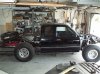
I have been experimenting with a catch can set up to see how it works.
this is only experimental so it it looks a bit neanderthal.
The 5/8 hose from the top goes to the RHS rocker cover.
The 5/8 hose from lower down goes to the intake before the throttle body.
PCV goes to the top of the can,
And the other hose at the bottom is vacuum.
Now I need help with this catch can system that is fitted because I am pressurizing the crank and have blown the rear main seal and is also leaking from the front seal, I was hoping it was plumbed up correctly, and if it is then something else has gone wrong.
The top hose should go to the intake and the lower come from the cam cover.
I think your problem is that bottom line - your source of vacuum. You didn't state where that's coming from, or what it's purpose is.
If that line comes straight off the intake manifold, then it's under positive pressure whenever you're on boost, and it's pressurising the crankcase via the line going to your RHS cam cover (and possibly also through the PCV system if you happen to have turned the PCV valve around the wrong way.)
It's too late now, but it would have been interesting to have had a pressure sensor in your catch can. I'd bet that every time you boosted the motor, you had positive pressure in that can, which is a no-no.
")