G'day all, Just trying to sort out my trans running a Haltech 2500 ecu. Having trouble with tuning the gear changes but that isn't the problem. problem i have is that i have no reverse. If i unplug the connector at the back of the trans for the solenoids reverse is fine. I have power at No1 solenoid while in reverse and also park. Is this correct? thinking it is a software issue
You are using an out of date browser. It may not display this or other websites correctly.
You should upgrade or use an alternative browser.
You should upgrade or use an alternative browser.
Haltech and A341e
- Thread starter Sudsy
- Start date
The 1UZFE EGR Delete Kit is available for sale here.


ivan129
BlownZX
- Messages
- 298
- Location
- Some where down under
There should be no solenoids powered when in Park, Neutral or Reverse. Solenoids 1 & 2 are used for selecting gears 1 to 4.
S3 is for TC lockup and S4 to reduce line pressure when shifting down gears.
S3 is for TC lockup and S4 to reduce line pressure when shifting down gears.
Thanks. Thats what i thought. Will have to search why it's happeningThere should be no solenoids powered when in Park, Neutral or Reverse. Solenoids 1 & 2 are used for selecting gears 1 to 4.
S3 is for TC lockup and S4 to reduce line pressure when shifting down gears.
ivan129
BlownZX
- Messages
- 298
- Location
- Some where down under
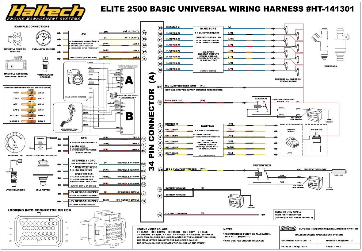
S1 & S2 have one side of their solenoids internally tied to chassis (Gnd) so to operate them you require a +ve voltage. From what I've read in the Toyota manual they can be operated using PWM signal but I saturate them with a fixed +12V. S3 & 4 have both side of the solenoid broken out to the connector so you can tie one side to Gnd and operate them with a High Side Driver (+ve) or connect them to +12V and operate them with a LSD (Gnd). Yours choice. Haltech have a really good TCU library however I use my own TCU. While I am using an elite 2500 myself for the UZ, I'm use my own controller that works fine for my application on my A341E. I do use 2 OP signals from the Haltech, (Kickdown & Light throttle to give me an early shift up under light load) otherwise the TCU takes care of auto shift, sports shift and manual shift, has some other stuff like colored display mounted in the dash for various modes of operation.
I used the DBW outputs for S1 and S2 operation. Also using Haltechs PRNDL controllers which was working ok until the other day when software had a bit of a meltdown. Will get onto Haltech tomorrow and see what they have to sayS1 & S2 have one side of their solenoids internally tied to chassis (Gnd) so to operate them you require a +ve voltage. From what I've read in the Toyota manual they can be operated using PWM signal but I saturate them with a fixed +12V. S3 & 4 have both side of the solenoid broken out to the connector so you can tie one side to Gnd and operate them with a High Side Driver (+ve) or connect them to +12V and operate them with a LSD (Gnd). Yours choice. Haltech have a really good TCU library however I use my own TCU. While I am using an elite 2500 myself for the UZ, I'm use my own controller that works fine for my application on my A341E. I do use 2 OP signals from the Haltech, (Kickdown & Light throttle to give me an early shift up under light load) otherwise the TCU takes care of auto shift, sports shift and manual shift, has some other stuff like colored display mounted in the dash for various modes of operation.
ivan129
BlownZX
- Messages
- 298
- Location
- Some where down under
DBW 1 & 2 ops should be fine. They are 5A peak and 1A continous drive current. The hold current for those solenoids will be around 1A. Have you tried using the Haltech diagnostic menu to look at the state of the DBW 1 & 2 outputs and AVI input when selecting gears. I assume the PRND box connects to an AVI inputs and outputs a different analogue voltage for each gear position. This can also be checked if you monitor the AVI pin also. If all seems fine then meter the pins, S1 & 2 and output from your PRND box to make sure the Haltech values are really correct.
I have a 2500 Elite running the auto - using DBW1 P1 & P2 - and it works perfectly.
Provided you have Toyota A340 selected as your transmission type, the software is programmed to use the shift solenoids in the right sequence. Are you using the NSP software?
Let me know if you need some help with your shift table - I've spent a lot of time on mine, and it drives very well.
Provided you have Toyota A340 selected as your transmission type, the software is programmed to use the shift solenoids in the right sequence. Are you using the NSP software?
Let me know if you need some help with your shift table - I've spent a lot of time on mine, and it drives very well.
Yes i have it all selected properly and using NSP software. I think the problem is that i have power at S1 whether in P R N and D. As far as i have heard only supposed to be powered in drive. Are you using the PRNDL unit from haltech?I have a 2500 Elite running the auto - using DBW1 P1 & P2 - and it works perfectly.
Provided you have Toyota A340 selected as your transmission type, the software is programmed to use the shift solenoids in the right sequence. Are you using the NSP software?
Let me know if you need some help with your shift table - I've spent a lot of time on mine, and it drives very well.
No, I made my own. $15 in parts from Jaycar and 30 minutes of soldering.
If your PRND2L switch is not configured correctly, it may be thinking you are in a drive gear, when you're not.
What does it show in your gear position value as you change through each gear?
When you say the software had a meltdown - what happened?
If your PRND2L switch is not configured correctly, it may be thinking you are in a drive gear, when you're not.
What does it show in your gear position value as you change through each gear?
When you say the software had a meltdown - what happened?
PRNDL shows correct gear when shifted. Even if i unplug it i still have 12v at S1. Is the one you made tuneable in NSP or fixed shifts? I did look around for something to build but couldn't find anything suitableNo, I made my own. $15 in parts from Jaycar and 30 minutes of soldering.
If your PRND2L switch is not configured correctly, it may be thinking you are in a drive gear, when you're not.
What does it show in your gear position value as you change through each gear?
When you say the software had a meltdown - what happened?
If you still have 12v @ S1 with the PRNDL box unplugged, it sounds like there is an issue with your ECU. It should not be putting out any power unless its in the forward shift pattern.
This is the box I made - it outputs the following voltages

This is the box I made - it outputs the following voltages
- P = 4.5v
- R = 4.0v
- N - 3.5v
- D = 3.0v
- 2 = 2.5v
- 1 = 2.0v
- OD = 1.5v
- Sport = 1.0v
Not sure if this option is available in your setup, but check if the shift solenoid wiring active state set to high or low.
High = Power is switched ON to activate the solenoid
Low = Power is switched OFF to activate the solenoid
Yours should be set to high - if its set to low, theres your problem.

High = Power is switched ON to activate the solenoid
Low = Power is switched OFF to activate the solenoid
Yours should be set to high - if its set to low, theres your problem.
PRNDL shows correct gear when shifted. Even if i unplug it i still have 12v at S1. Is the one you made tuneable in NSP or fixed shifts? I did look around for something to build but couldn't find anything suitableNo, I made my own. $15 in parts from Jaycar and 30 minutes of soldering.
If your PRND2L switch is not configured correctly, it may be thinking you are in a drive gear, when you're not.
What does it show in your gear position value as you change through each gear?
When you say the software had a meltdown - what happened?
They were set to low originally but sorted that quite a while ago. I'm suspecting the ECU also as for some reason i have 4.5 v on the grey and red wire when the ecu is switched off. I spoke to Haltech and he told me to check all my sensors and wiring. I not thinking did that and opened up the loom to check everything then realizes that there won't be any voltage to the sensors with ECU turned off. Have to wait till next week now to get any sense out of them. Wasted a few days on that excercise as as everything is fitted in the kick panel in 37 Chev and wiring goes through the floor to the engine bay.Not sure if this option is available in your setup, but check if the shift solenoid wiring active state set to high or low.
High = Power is switched ON to activate the solenoid
Low = Power is switched OFF to activate the solenoid
Yours should be set to high - if its set to low, theres your problem.
View attachment 25743
ivan129
BlownZX
- Messages
- 298
- Location
- Some where down under
It would help us, to help you, if you could identify the ECU pin (name or number) that the grey and red wires are conneced to and what they are wired to. Not sure if this is part of your problem but.... HSD outputs use the Gnd as the common. Sensors, (CLT, IAT, etc) use the sensor Gnd as the common or return. These 2 Gnds should not be connected together as they can cause the ECU to behave strange. 2 wire sensors usually require the pullup to be enabled at the ECU as they are just variable resistances to the sensor ground and need the pullup to complete a voltage divider that the ECU then reads from the changing sensor resistance. Hope this helps
The grey and red wires are 12v+ from the ecu once ign is on. They feed anything that needs 12v with ign onIt would help us, to help you, if you could identify the ECU pin (name or number) that the grey and red wires are conneced to and what they are wired to. Not sure if this is part of your problem but.... HSD outputs use the Gnd as the common. Sensors, (CLT, IAT, etc) use the sensor Gnd as the common or return. These 2 Gnds should not be connected together as they can cause the ECU to behave strange. 2 wire sensors usually require the pullup to be enabled at the ECU as they are just variable resistances to the sensor ground and need the pullup to complete a voltage divider that the ECU then reads from the changing sensor resistance. Hope this helps
ivan129
BlownZX
- Messages
- 298
- Location
- Some where down under
ivan129
BlownZX
- Messages
- 298
- Location
- Some where down under
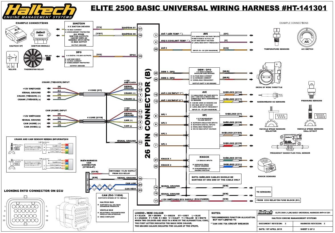
Read your post again. The only switched 12V that comes from the ECU when the ignition is switched on to drive stuff, comes from the ECR. When the ign. is switched on, the ECU applies a Gnd via DPO6 (A25) to the ECR to operate it. The ECR in turn applies 12V to power things, injectors, ign coils etc.. If this is where your Red and Grey wires are connected and your measuring 4.5V when the relay is released, you have something thats back feeding voltage to these. Isolate the things connected to it/them one at a time until the voltage drops to 0V and then back track where its coming from. It would be helpful if you had a wiring diagram to post and identify where you think the problems is. Hope this helps.
Attachments
I have 10v at DPO6 which should be earth switched when key is on. This is a haltech premium loom. Only place that can be coming from is the ecuRead your post again. The only switched 12V that comes from the ECU when the ignition is switched on to drive stuff, comes from the ECR. When the ign. is switched on, the ECU applies a Gnd via DPO6 (A25) to the ECR to operate it. The ECR in turn applies 12V to power things, injectors, ign coils etc.. If this is where your Red and Grey wires are connected and your measuring 4.5V when the relay is released, you have something thats back feeding voltage to these. Isolate the things connected to it/them one at a time until the voltage drops to 0V and then back track where its coming from. It would be helpful if you had a wiring diagram to post and identify where you think the problems is. Hope this helps.
ivan129
BlownZX
- Messages
- 298
- Location
- Some where down under
Sorry, I'm not familiar with the Haltech loom. I made my own to fit my elite 2500. Re-pinned a Wolf V550 loom to Haltech.
I've found Haltech stuff to be pretty good, but hey they are just humans.
I agree you should read close to 0V on DPO6 when the ign. is on. The reason why I say close to zero volts, will depend on how hard the driver switches to ground with the load you have on it, and if its just a normal relay then it should be pretty much 0V. If the load was say 10Ohms, then you might read a couple of volts as the driver can only push 1A to supply.
However there are other conditions that must be met for you to see a switched Gnd @ A25 (DPO6) and switch the relay on. Most 12V relays will operate with about 8Volts on them and will hold down to about 6V
The only thing that should be connected to A25, (DPO6) is the ECR relay coil (pin 85) and the other side of it (86) connects to battery. The relay coil should measure approx 120 - 200Ohm between 85 & 86.
1) You must also have a Gnd on A10 & A11.
2) You must have ign. switched +12V on A13.
If the above checks out, I would disconnect the ECR relay (85) from A25 DPO6 and connect a low wattage test lamp (something that drags less than 1A) to A25 and the other side of the test lamp to battery. Switch the ignition on (ie. power on A13) the test lamp should light. Measure the voltage at A25 (should be your Gnd). If that works then you got something else connected to DPO6 loading to battery +ve.
That is DPO6 doesn't have enough balls to drive to ground cos of the load is pulling it to battery.
If you were close by, I drop round and give ya a hand, but SA is a little way a way.
Good luck. Hope this is of help.
Similar threads
- Replies
- 5
- Views
- 1K
- Replies
- 0
- Views
- 2K
- Replies
- 1
- Views
- 2K
- Replies
- 18
- Views
- 10K
- Replies
- 3
- Views
- 3K
- Replies
- 11
- Views
- 13K