Standalone ECU 1UZFE 36-1 Trigger Wheel and Megasquirt

The 1UZFE EGR Delete Kit is available for sale here.
Here is the 60 teeth wheel Cribbj requested. This is only possible with water jet. Laser would not able to cut this fine and precise. Here are two pictures...


P.S. I will send that to you in couple of days.....
 
The 60 tooth was a special request by our Super Moderator. The 32 tooth wheel and all other drawings doesn't belong to me. My shop would NOT release them to me. Those cads files belong to the shop. They are not mine.

As for the 32 tooth. I would need 5 orders in order for me to do another trip to the shop.
 
Dave got the trigger in the male yesterday, fantastic thanks.

I've been playing around today fitting the wheel and have come to a few conclusions:

I measured the bolt though hole diameter at ~3.8mm, knowing that I can't have any protrusions out the back of the trigger wheel, I decided to thread the rearward wheel, as any rearward protrusion would space the trigger wheel away from the crank cam belt drive sprocket.

So I drilled the rear section to 4.2mm and tapped to 5mm metric course. I then drilled the forward wheel to 5mm to clear the m5 allen head bolts. What I did notice when I installed the trigger wheel on the crank snout was the heads of the allen bolts were stopping me from pushing the dampener all the way home against the front face of the rearward wheel.

I threw the wheel in the lathe and turned down the interfering parts of the allen head bolts, but I realize that this isn't an option for everybody, so unless I've missed something here you might want to get the laser cutters to position the holes on a larger radius.

I also notice that there was some axial movement on the crank snout when the wheel was mounted, so I got out my trusty verniers and took a few measurements. The standard Toyota trigger wheel's key way measured in at 4.95mm. The "lex wheel" measured in at 5.05mm, 0.1mm bigger. I don't know the tolerances that the laser can cut to but you might be able to close the gap and decrease the axial slop, though once the balancer is tightened down the wheel shouldn't go anywhere, but accurate location is important.

The only other potential issue I can see is the the rearward wheel is cut from 3mm sheet, the original Toyota piece is 2mm here, this will space out the balancer 1mm forward of its original position, you don't loose enough key way engagement to worry about but you do push the pulley out a little. I don't have enough experience with multi rib serpentine belts to know whether this is going to be a problem or not, I suspect not though.


Anyhow great wheel and I one step closer to starting her up now thanks to you and cribbj

Dave got the trigger in the male yesterday, fantastic thanks.

I've been playing around today fitting the wheel and have come to a few conclusions:

I measured the bolt though hole diameter at ~3.8mm, knowing that I can't have any protrusions out the back of the trigger wheel, I decided to thread the rearward wheel, as any rearward protrusion would space the trigger wheel away from the crank cam belt drive sprocket.

So I drilled the rear section to 4.2mm and tapped to 5mm metric course. I then drilled the forward wheel to 5mm to clear the m5 allen head bolts. What I did notice when I installed the trigger wheel on the crank snout was the heads of the allen bolts were stopping me from pushing the dampener all the way home against the front face of the rearward wheel.

I threw the wheel in the lathe and turned down the interfering parts of the allen head bolts, but I realize that this isn't an option for everybody, so unless I've missed something here you might want to get the laser cutters to position the holes on a larger radius.

I also notice that there was some axial movement on the crank snout when the wheel was mounted, so I got out my trusty verniers and took a few measurements. The standard Toyota trigger wheel's key way measured in at 4.95mm. The "lex wheel" measured in at 5.05mm, 0.1mm bigger. I don't know the tolerances that the laser can cut to but you might be able to close the gap and decrease the axial slop, though once the balancer is tightened down the wheel shouldn't go anywhere, but accurate location is important.

The only other potential issue I can see is the the rearward wheel is cut from 3mm sheet, the original Toyota piece is 2mm here, this will space out the balancer 1mm forward of its original position, you don't loose enough key way engagement to worry about but you do push the pulley out a little. I don't have enough experience with multi rib serpentine belts to know whether this is going to be a problem or not, I suspect not though.


Anyhow great wheel and I one step closer to starting here up now thanks to you and cribbj


Thankyou


have fun


Simon


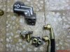
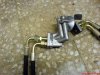
P.S. if this is clear as mud I'll post some pics for you.
 
Thanks Simon for the great feedback. By the way, you double post in your thread. Once everything in it should work ok. Now the wheel is done, we need a MS unit that will work with 1uzfe ignition system.
 
Now the wheel is done, we need a MS unit that will work with 1uzfe ignition system.

David, you don't have to go full MegaSquirt; there's a dedicated ignition controller called the MegaJolt Lite Jr. This sends all the necessary signals to a Ford EDIS8, so for probably less than $250 US you can dump your dizzies and go full crank triggered ignition (albeit waste spark). This is what I'll be doing for the engine dyno break in of my 1UZ.

Here's the MegaJolt Lite Jr. website: http://www.autosportlabs.net/Main_Page

They even have basemaps you can download into your controller for a starting point.

The one disadvantage to this setup is that it doesn't accommodate any knock sensors.
 
I'm with cribbj on this, to make the system more reliable the first thing you want to do is get rid of the dissys. They are a high maintenence item that needs semi-frequent replacement. Moving parts are alot more likley to give you troble than anything solid state like the EDIS ignition system.

have fun

Simon
 
dissy

I'm with getting rid of the dissy' also. :sleeping: Just do a 36-1 wheel and do edis with megasquirt. It works well and is very reliable. BTDT
 
Mated my two part trigger wheel today, and covered a lot of the same ground Simon did (I should have reread your post about the heads of the Allen screws interfering with the dampner hub!!)

I initially tapped both wheels with an M4, however the threads were too fine and not deep enough, so I retapped the trigger wheel with an American 6-32 and just opened up the keyway wheel to fit and it's perfect. Used flathead screws and countersunk the heads into the keyway wheel, so no head protrusion on the rear, although I'm going to mill down the back surface a tad to be sure.

IMG_0729Large.jpg

Now to grind off the correct tooth to make the "missing tooth", which by my calcs is tooth #14, going clockwise, after the keyway.

IMG_0730Large.jpg

For a V8 engine, using the EDIS8, the trigger wheel is lined up like this:

"With #1 at TDC, the missing tooth shall be 50 degrees (5 teeth) ahead of the pickup"

So in other words, the missing tooth has already passed the pickup by 5 teeth. As a double check, count the missing tooth's position from the pickup, using the tooth directly under the pickup as #0, and the missing tooth should be #5.

IMG_0727Large.jpg
 
runout

Looking at the pictures, I don't see any step that would center the wheel. How did you do that? The reason that i brought this up is to let everyone know that it is very important that the trigger wheel not have excessive runout.I don't know how much is too much, just that if is too much, the edis module will never sync to the wheel.
 
Jack, the holes were already precut in both the keyway wheel and the trigger wheel, so I'm thinking/hoping they were done with enough precision that there'll be little or no runout. Guess we'll see.

Since you've already done these with the OEM 36-2 wheels, does it look like I've picked the right tooth for the "missing" one, ie 140 degrees clockwise from the keyway?

How did you center the two parts together before you drilled and taped the holes? Regarding the missing tooth, it needs to be 50 degrees btdc. I'm not sure how that relates to the keyway.
 
I'm still trying to get this figured out - you need 5 for an order, I'd like one, you said that you still need a few more.

how many more commitments do you need to get to 5 so that you can do an order? gotta be a number between 1 and 4
 

Attachments

  • DSC00624.jpg
    DSC00624.jpg
    59.9 KB · Views: 52
  • DSC00625.jpg
    DSC00625.jpg
    63.4 KB · Views: 41


Top