- Messages
- 5,632
- Location
- Sydney, Australia
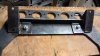
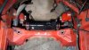
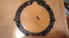
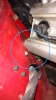
Given the rails must be around 500mm apart are you concerned the plate could flex at all?
By this I mean it can rise and fall which would allow the rails to move in and out.
I'd be leaning toward some sort of gusset running across the plate to add to its stiffness. Probably right across the front of it.
What has your Engineer said about the plate?
By this I mean it can rise and fall which would allow the rails to move in and out.
I'd be leaning toward some sort of gusset running across the plate to add to its stiffness. Probably right across the front of it.
What has your Engineer said about the plate?
") .
.