I know wiring autos to aftermarket ECU isn’t a common thing and not many have any experience with these as yet, but I have a couple of questions someone might be able to shed some light on.
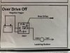
I worked out the Pinouts from a map I managed to find and it has an input/ output Setup for an OD wire, which I presumed would just go to the overdrive switch and to ground As there is already a wire to control the t/c lockup solenoid. But someone has thrown me, in that it possibly needs power and go through a relay, unfortunately there is no wiring diagram for the wolf Tuner series and no documentation for setting up and wiring the auto box.
my second question is the speed sensor, it’s an early crown three wire which has power, earth and vss, I get that the speed signal goes to the speed input but does the sensor power and earth have to go through the ecu, Or can they just be supplied 12v and run to a ground? Also does anyone know how to setup the speed sensor configuration on a wolf Tuner series or V550 as the setting I have are for a Soarer and the crown is different and has 20 pulses.
and lastly do the ECU ground wires have to go to the engine block or can they be run to a main earthing block or back to the battery?
Any help really appreciate.