Supra/Soarer rear geometry

The 1UZFE EGR Delete Kit is available for sale here.

Matty Dog

New Member
Messages
29
Location
Wellington, New Zealand
I am in the process of building something along the lines of an over-sized, 1UZ-powered Lotus Seven, using front and rear suspension from a Mk3 Supra. It looks like a strong, well-designed set-up and should suit my purposes well after trimming some of the excess weight off the sub-frames.
My one concern with the Supra rear end at the moment is the location of the forward-facing trailing arms. In their present location, the front mounting will intrude directly into the space where the driver and passenger would sit.

I want to move the front mounts for the trailing arms outwards, but I can’t figure out what effect this will have on the car’s handling.

I have talked to a couple of knowledgable people in my car club who clearly have a good understanding of how suspensions work, but I was not able to reach a conclusion.
One said that as the suspension only has limited travel in the sort of car I am building, so I could put the mount where I want it to be and it would have a negligible effect.
The other guy suggested that the current location of the trailing arm would probably induce a little understeer under hard cornering, which isn’t always desirable, but that changes should be thoroughly researched.

If the car had a regular double-wishbone suspension, I think this would be simpler to resolve, as I could just mount the trailing arm on the trajectory line from the two lower wishbone pivot points (sorry if I’ve lost anyone here, I’m a mouse-clicking banker, rather than an engineer!).
Being a multi-link set-up, I just can’t figure out what the implications of any changes will be.

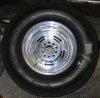
The picture below is from www.MA70.com and depicts the Supra rear suspension to give you an idea (hopefully!) of what I am working with.
 
You should definately hit the CAD! I'm no expert but... i'm under the impression that the forward links just take up a major part of the load path to control front-rear wheel movement. Given that the links are the same length, if you remount them outwards you should have no problems with abnormal wheel movement (most likely dealing with anti-squat?). However, because the links will have a natural arc to them while in movement, the height will be your main concern (given that again... the links are the same length). The other links will function as a double wishbone, and control toe/camber independent of the forward link changes.
 
Hello Matty Dog;

You're in the process of building "an accident looking for a place to happen". The links you are referring to have to be located in the correct location (like the stock position in relation to how the rear end is mounted) otherwise you end up with all sorts of hideous problems with the rear suspension.

Not only are the links designed to be in a specific location in relation to the rest of the rear suspension, the angle of the links determines whether or not the rear end steers you off the road in a turn, and the compressibility of the bushings determines compliance as well.

Most independent rear suspensions are variations of the semi-trailing arm rear suspension developed in Germany (why pre-90s BMWs were death in the rain and oversteered horribly under trail throttle braking) and still used on BMWs, some Porsches, and M-Bs. Basically, the only worse rear independent suspension that could be used is the pure swing arm suspension found on early puke bugs.

Since it is impossible to make a semi-trailing arm rear suspension do what needs to be done, all sorts of engineering compromises have been "band-aided" on (like bushings with different compliance, and "multi-link" rear suspensions) and a LOT of marketing hype has been liberally applied to try to convince people that this abortion is actually something that works.

However, when properly done (as in keeping the suspension design in the car it came with), these abortions actually do work rather well, and most of the bad stuff has been compromised out. There are several well developed rear suspension systems that work when properly designed: MacPherson independent rear suspension (240Z), double wish-bone (Pantera), semi-trailing arm (most cars with independent rear suspensions), asymmetrical, semi-elliptical leaf spring (the best), solid axle (most fwd cars).

If you are just looking for strength in the rear end, use the TT differential, but keep the rear suspension that came with the car. Front suspension design is difficult enough; rear suspension design is really difficult, because a unpredictable rear suspension is a killer.

Mike Martin
 
Did you ever get an answer to you question Matt Dog. Here is my 2 cents worth of opion. The rear trailing your talking about is not used for suspension geometry, but more to keep the control arms from buckling. A-arms/ control arms are designed only for compression and tension, not buckling. When the car accelerates or deccelerates, a torque is geneatated and wants to twist the upright in parallel with the axis of half shafts. To counter act this torque, the trailing arm is there. When the guy said that it will create an understeer during hard cornering. First under steer can be changes by changing the stiffness of the suspension. Usually done with tires pressures, anti roll bars, spring rates, or track width. So do be worried about that, you can tune it if you are patient. If you are still going to use this suspension, my suggestion is that when you do shorten the trailing arm, keep at the same angle( created between the wheel and trailing arm) and try to position the pick up point so the arm is level ( with respect to the ground) when at ride height.
 
Twist the upright in parallel with the axis of half shafts.

I mean to say around the axis of the half shafts, sorry
 

Attachments

  • Picture-018small.jpg
    Picture-018small.jpg
    62 KB · Views: 5
The suspension shown in the pic is (near) parallel lower links (2), with a forward running control rod and "A" upper link.

If you modified the 2 lower links to be equal length and parallel at 90deg to car centreline, the control rod front mount can be moved out with no adverse effects. There will be no measurable toe change with movement. There will be no roll resistance change due to geometry ( as there is now).

The angle of the control rod relative to the ground will control anti-squat/lift. More angle up to front,more anti-squat/lift. Angle down to front,pro-squat/lift.

There is no torque moment under acceleration around the rear axle, that is taken out by the diff housing. You do have an offset load distribution because of the different lengths to pickup points. This load is reacted through the control rod and the upper "A" arm.

There is a torque reaction under brakes and this reacted through the same control rod and "A" arm.

If you have the lower links horizontal at ride height, roll centres should be in the ball park.

Designing rear suspension geometry is no harder than front geometry, the trick is keeping them in "sync".
 
Yup, you want to keep the front roll center in the same relative place as the rear suspension, as it came in the original vehicle.
 
Thanks for the responses. particularly Vinnito, rms and SCV8 who do not forecast certain death!

Since posting my original question, I have read into the subject and come up with a few possibilities, and I was hoping for some more feedback.

I traced the photograph from my initial post and made some very crude lower-arm sketches in Adobe Illustrator.
The lines in yellow represent the chassis of my project (roughly).
In all cases, the top wishbone is left as it came from the factory.

The first picture is the stock set-up, for reference purposes.
As you can see, the forward mount for the trailing arms intrudes into the cockpit.

The second picture is an idea I got from seeing a car where a FWD drive-train (Mini) was being used at the rear of a car in a mid-mounted position.
There is a a control-arm rose-jointed onto the wishbone, and can be adjusted for toe in and out.
The idea is that the multi-link rear suspension is transformed into a regular double wishbose set-up, albeit adjustable.
The trailing-arm, in it's new position, is attached to the hub with a rose-joint.

The third picture is similar to the second one, however, the wishbone is over a wide base, like a 1960's F1 car, eliminating the need for a trailing arm.

Lastly, I have a reversed wishbone arrangement.
The trailing-arm, in it's new position, is attached to the hub with a rose-joint.

I don't know if any or all of these suggestions could be made to work.
I would welcome any feedback.

RMS: I like the idea of making the two lower links the same legnth and parallel, but it would appear that the outer ends are at different distances from the centreline, so I'm not sure how this would affect things.

Cheers,
Matthew
 
Figure 2 can not use a trailing arm, it is the same as figure 3. Fore & aft translation of the wheel is controled by the wishbone. The major disadvantage of both is that a line through the inner pickups is not parallel to the centre line of the car, bump & droop will introduce toe changes.

Figure 4 will also introduce toe change with bump & droop.

In a parallel link setup the outer ends at different distances from the centre line will not change anything, so long as they are equal length, 90deg to centre line and parallel. It will remain a parallelogram with for/aft translation of the wheel. Rotation of the upright caused by the trailing link during bump/rebound will twist the parallelogram but the toe change will be thouandths of an inch.

This system was the preferred option with formula cars untill packaging constraints and aerodynamics forced a change
 
Thanks for that.
This is the sort of discussion I have been looking for.

My preference is to eliminate the trailing arm altogether, if possible.
So, given what you have suggested, if I were to make both the inner pick-ups equidistant from the centreline, do you think the wide-base wishbone arrangement would be effective?
Is there any way to introduce some sort of anti-squat into this type of set-up? (Just to confuse the matter more!).

Matthew
 
Not to sidetrack your very interesting thread Matty Dog, but are there some recommendations for suspension design books?

I'm currently looking at Steve Smith's "Advanced Racecar Suspension Development" and Forbes Aird's "Race Car Chassis: Design & Construction"

TIA
 
Mathew,
Wide base wishbone is OK, don't mount toe link in the middle of a tube though (bending loads),toe link needs to have spherical joints at both ends.
Some anti squat can be achieved by raising the front inner pickup point, how much ? Trial and error, multi holed bracket.

"Sports & racing car chassis design" by Costin & Phipps covers the basic fundamentals and has formula's to calculate C of G, weight distribution, roll centre, roll resistance, restoring moment etc and basic stress calculations.
Might be a bit "old hat" these days but first you have to get the basics right.
 
Thanks, I'd forgotten about that one. It was the "Bible" for modeling suspension design when I was at University. Just picked up a copy from Amazon.

BTW, more relevant to this thread, there are some suspension modeling programs available from Performance Trends (the people who also sell Engine Analyser Pro) here: http://www.performancetrends.com/download.htm No idea how good they are, but if they're anything like EAP, they're probably fairly useful.
 
I would go with something like figure 2 has displayed, while maintaining the original relative angles(relative to the ground plane).
This will eliminate costly, and risky fabricating in this critical area, and basicall keep the suspension as it was.
I'm assuming the vehicle will have a stiff suspension anyways, this will help with geometry issues in any IRS that doesn't have the "perfect" setup.


Top