Peewee
New Member
- Messages
- 2,635
- Location
- Perth, Western Australia
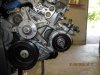
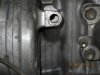
Rod, the alternator on post #609 has been dropped. 100% guaranteed.
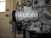
The alternator on post #615 is undamaged.
The alternator on post #615 is undamaged.
")

 I can't think of anything from the engine that can handle over 500 psi. BP company should hire you to conduct testings on hydraulic pressure before their drilling the oil wells. LOL.
I had that aircon problem on a 1uz I had years ago, and think it was because I was trying to use a crown compressor on a soarer motor??