CAD drawing for intake manifold flange

The 1UZFE EGR Delete Kit is available for sale here.

vqpwrd240

New Member
Messages
9
Location
Vernon Hills, Il.
Hi guys.

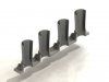
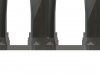
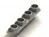
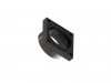
I am finally starting to work on my 240Sx with an early 1UZ swap. I plan on running a custom intake with Hayabusa ITB's. I have read some the other posts and saw that someone has the cad file and said the Hayabusa ITB's will work. I am wondering if anyone has this drawing and would be willing to send me a copy. I am also tried to pm one other member that was working on this. Any help woulf be great. Thanks in advance.

Ferhan
 
the flanges for the 1uz are no easy task, even if you do have the cad file. You will need a cnc machine with a 4th axis in order to make them properly.
 
I sent Autronic a pm, but did not get a reply. I am aware of that as well. I do have a person that will be able to make the changes if needed and then get them made. I just wanted to have something to start with. Thanks,

Ferhan
 
Hi
I also sent an email but not got any reply, I have access to a machine shop with the right machines, just need the drawing / cad file.


Alan
 
I was hoping to get the CAD plans, not to make as is but seeing as I don't have the machine shop required to do it and IMO it's going to be both tricky and expensive I was considering making each one 5 parts (per bank), one baseplate and 4 adapters.

Basically I think like these are (except they are 'complete' and using the existing injectors rather than using bike ITB's). http://atpowershop.co.uk/catalog/lexus-1uzfe-throttle-bodies-direct-head-p-165.html

Base plates I can get watercut for not that much then 8 relatively simple adapters I can turn up in the lathe, drill a few holes (trickiest will be the angled ones to mount to the head), tap 16 of them and then do port matching between the turned parts and the base plate by hand grinder. Rather labour intensive but ~£30 in materials and should still be easier than cutting up the existing runners.
 
Hopefully without being too cheeky, assuming your finals are now over and you have recovered from the following parties is there any chance of those CAD plans?
 
I'm finally done with my finals....

Ok, about the intake for the Hayabusa ITB's.

I had a look at it earlier today and there is a major issue, the Hayabusa ITB's are to tall.

Let me explain. The Hayabusa ITB's are tall, this + the intake adds up to interference between the
two banks of ITB's, they will touch when air horns are added.

I have tried to make the intake as short as possible, but a certain length is needed as the Hayabusa
ITB's are held in place with short hose ends towards the intake + you have a transition from round
to oval inside the intake as well.

Yes I can send you guys the drawings but they are not as finished as the other intake I have drawn,
as I didn't bother when I found out about the problem above.

If you like to receive the drawing send me an PM, but DO remember to include 2 things:

- Include your e-mail address.

- Tell me if you will make it on a mill or in a lathe.
 
Last edited:
Well, no answer from Autronic. So I did them myself.

As per my previous post, this was what I had in mind, although I'm using GSXR1000K2 rather than hayabusa so 42mm butterflies.

The adapters would then just be sealed to the plate with O-rings.
 

Attachments

  • ITB_inlet_manifold.jpg
    ITB_inlet_manifold.jpg
    65.2 KB · Views: 80
  • ITB_flange_1.jpg
    ITB_flange_1.jpg
    34.3 KB · Views: 63
Last edited:
Looking good. Just wondering how you would be connecting these to the actual throttle bodies? Are the Hayabusa TB's different then the ones you are using? I have not measured them just yet. Thanks in advance.

Ferhan
 
They're not substantially different, originally I was going to mount them exactly as they are on the GSXR1000 (and hayabusa). Although a number of people just use a bit of silicone hose clamped on it's not the neatest.

Then while googling I came across someone else using GSXR1000 TB's who instead just used an O-ring to seal and held them in place with a clamp. I thought it was such a good idea I decided to copy it ! :)

As an aside I also realised that on the later bikes they're actually now using flanges. They're pricey (about (£360 a set of 8) but would make a very simple solution, two plates, water or CNC cut, a set of flanges and two sets of throttle bodies. No complicated machining, the trickiest bit being spacing the TB's out.
 
Sorry about the poor modelling but very very quickly modelled some TB's to show what I mean.
 

Attachments

  • ITB_inlet_manifold_2.jpg
    ITB_inlet_manifold_2.jpg
    57.8 KB · Views: 58
  • ITB_inlet_manifold_3.jpg
    ITB_inlet_manifold_3.jpg
    45.9 KB · Views: 53
I was considering get a flange made for the tb's and have it welded to tb's. Then I can bolt it all together.

How thick are the two parts together in your first picture? Thanks again.

Ferhan
 
If anyone is still interested in the ITB setup you may consider looking at zx12r throttle bodies, they can be separated and are fairly short.

Sean


Top