1UZFE - VVTi - 98 LS400 wiring diagram

The 1UZFE EGR Delete Kit is available for sale here.

V8allisonSA

New Member
Messages
6
Location
South Africa
Hi guys, my name is Warwick. Posting all the way from South Africa. Wanted to ask if anyone doesn't perhaps have a wiring diagram for a 1998 to 2000 1UZFE VVT-i - LS400. Any help would be greatly appreciated.
 
Where to begin

Hi George, thanks for the help. According to a source here in SA, I'm missing part of the harness from the ECU. Please see attached. Do I need the missing ones or can I make them up? What are the plugs for that are missing?
 

Attachments

  • 20150308_123800 (576x1024).jpg
    20150308_123800 (576x1024).jpg
    177.1 KB · Views: 47
ecu power, transmission range input, sub o2 sensors, passenger side vvt control solenoid, engine immobilizer system
yes you can make it up
 
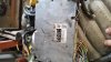
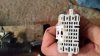
EB1 wiring plug and relays

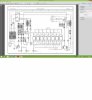
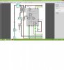
Hi George, could you assist me with a query. I notice on the factory wiring diagram, the power source supplies the ignition with power via plug EB1. I take this to be the cluster and dash instruments part of the wiring harness. Does this mean that I am first to supply power to this loom on the appropriate pins as indicated on the drawing. After this am i then to supply power to the ignition switch from the same loom plug (EB1) to the ignition switch? I.e. The starting & ignition diagram - 40A fusible link to EB1 (Pin 4) & 30A fusible link to EB1(pin 15) - thereafter (Pin 2) EB1 to AM1 & (Pin 7) EB1 to AM2..? Is this correct. What is AM1 & AM2? I cant locate these in the manuals??

Further to the above. Are all the relays in the diagrams, 30A Normally Open?
 
You are over-complicating things

ignition system and injectors (as well as IGSW pin of ECU) are powered from ignition switch
BATT pin of ECU is powered from battery

the rest is powered from main relay's output. You can place a number of fuses rated at 10-15A quite randomly across the power supply system, using only common sense.
 
wiring plug and relays

I've followed the attached drawings as simply as possible, using as much common sense as possible. Please see the attached. This plug (pic attached) is just loose on the loom (looks to me like EB1??) which the drawing states certain pins within this plug receive power?? My motor looks the same as the motor used in your custom build of the Volga.
 

Attachments

  • Starting & Ignition.jpg
    Starting & Ignition.jpg
    20.5 KB · Views: 94
  • Engine Control & Immoboliser - Colour.jpg
    Engine Control & Immoboliser - Colour.jpg
    18.3 KB · Views: 82
  • 20150308_124726 (576x1024).jpg
    20150308_124726 (576x1024).jpg
    125.1 KB · Views: 48
I'm afraid the attachments with the drawings are too small (not readable)
The plug that you hold on the photo is used to power up engine side of the loom, and also it has some signals that you will need to connect to your ECU.

When doing my conversion, I never relied on junction names, etc. Just looked at wiring diagram and used multimeter
 
wiring plug and relays

Could you send me an email address then I could show you the drawings and I could mail u a few pics of the wiring as I've got it hooked up at the moment? Really battling here.


Top